Gascoigne Wood Underground.

The spine tunnel developments at Gascoigne Wood were the longest and most complex mining developments ever undertaken in the UK. The south spine Robbins T.B.M. was the first to be completed on 22nd June 1987. The north spine tunnel, driven by a Thyssen Meco ( Paurat ) Titan E134C Roadheader, was completed on 24th November 1990.

The south spine tunnel was equipped with 14,885 horsepower ( 10,100KW ), 1.3m wide, 28.1mm thickness, steel cord conveyor capable of carrying 2200 tonnes of coal per hour at a speed of up to 8,4m/sec . It was 12,232m in length and weighed 2,500 tonnes when empty and transported coal 805m from lowest point to surface. The drive was a Direct drive, twin E frame DC winder motors (5050kw) and was  designed by Anderson Strathclyde and REI and was the most powerful conveyor in the world when installed.

Information plate on A.S.L.Conveyor Drive

It was designed to handle the entire coal production of the Selby Coalfield and was the first of the spine tunnels to be fully operational.

Gascoigne Wood South Spine Steel Cord Conveyor.

The North Spine tunnel, when operational was equipped with a 11,084 horsepower (8750 kw), direct drive, twin D frame winder motors rated at 4375 kw, 1.05m wide cable belt. The length of the conveyor was 9,650m with a tandem accelerator conveyor, 3,000m in length and 1.35m wide, loading from the inbye end, on to the cable belt.

The Cable Belt Tandem Conveyor.

Both conveyors were capable of 2,000 tonnes per hour. It was designed by Cable Belt Conveyors Limited and was also capable of handling the full production of all the five mines.

Wistow Staple Bunker delivering coal on to the cable belt.

Deputy inspecting the cable belt

When the Selby Complex was fully operational the Gascoigne Wood spine tunnels were fed from the five producing mines via multiple vertical bunkers. The staple bunkers were supplied with coal from the Barnsley seam which is 60m above the Gascoigne Tunnels.

During production the Gascoigne Wood conveyors had to run constantly and stoppages were very rare due to the sheer amount of production from the five mines. Any stoppages, other than safety related , were planned so that production could be re- directed to either of the main conveyors. At the bottom of each staple bunker, a monitored and controlled feed of coal was achieved using Westerland Feeders. These feeders had load cells so coal feeds could be measured and controlled. All the bunkers were controlled by Gascoigne Wood surface control room. The feed of coal was delivered via hoppers with hydraulic doors, each with a capacity of 85 tonnes and could direct the coal supply to either of the spine tunnel conveyors. During the spine tunnel developments a system of boreholes from Wistow Mine to Gascoigne were planned for access. The borehole at V3s was a small bore staple shaft. The next cross slit at V4s was originally a single bunker but later became West and East staple bunkers, at 4.5m diameter, each with a Westerland weigh feeder. The coal clearance from Wistow Mine to Gascoigne Wood Mine started in January 1983 in order to start production at Wistow Mine in July 1983.

Wistow Mine staple bunkers and boreholes

As the Gascoigne Wood spine tunnels progressed further staple shafts and access shafts were made. At 7208m a ventilation shaft from Wistow was made. The next cross slit was called V7s where a staple shaft was sunk. The next cross slit was V8s where two staple bunkers were sunk with access ladders to Wistow Mine.

V8s Heading during construction.

V8s cross slit when completed.

Vent slit during construction.

This cross slit had a north and south staple bunker when completed. Just inbye of this slit at 7916m, a second ventilation shaft was constructed and the shaft at 7208m was disused.

Wistow Mine staple shafts and boreholes

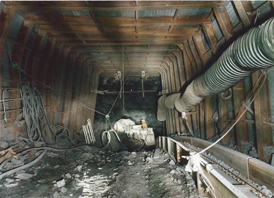
The south spine Robbins TBM tunnel progressed very well , but the north spine tunnel slowed due to very bad ground conditions which required back ripping at a later date.

Amco heading men back ripping in South Spine Tunnel.

In early 1986 The south spine Robbins TBM heading broke the world record for a Tunnel Boring Machine when the AMCO heading teams mined a record of 19m in one shift, 43m in a day and 152.4 metres in a week breaking a record from 1981.

The world record breaking AMCO Heading Teams January 1986

The next production connection was with Stillingfleet Mine. This staple bunker was a revised version of original plans to have dedicated staple bunkers at Stillingfleet Mine and North Selby Mines. The revised plan was to have a conveyor through Stillingfleet Mine from North Selby Mine and deliver the combined production through one staple shaft when North Selby was in full production.

Stillingfleet / North Selby Connection.

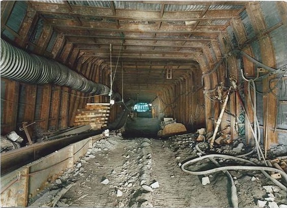
The south spine tunnel progressed well until late 1986 when the TBM hit very soft conditions. The tunnel boring machine was unable to cut in the soft rock and virtually stopped. A connection with Riccall Mine was imperative as the coal production from Riccall and Whitemoor Mines depended on Gascoigne Wood for the coal clearance. The only answer was a heading from Riccall Mine back towards Gascoigne Wood so a heading started from Riccall Mine in early 1987. The Stillingfleet Connection heading was well established, when the south spine TBM overcame the soft conditions using a concrete grouting system. The heading progressed well to the final point and completed the spine tunnel on the 22nd June 1987.

Gascoigne Wood Spine Tunnel connection with Riccall Mine at completion of both Spine Tunnels.

As you can see from the plan above the ventilation borehole, access borehole and coal clearance staple shafts are shown.

A 1in 7 drift connection was made from Riccall and booster fans were installed and powered from a dedicated supply in Riccall Mine pit bottom substation.

To ensure the safe access and egress in and between the spine tunnels at Gascoigne Wood Mine, cross slits were made as mentioned in a previous post. These were used for ventilation, substations, loco pass byes, charging stations, for the locomotive fleet, pumping stations, staple bunker access and ventilation/ access boreholes. To enable the safety of the men in the case of a fire in the spine tunnels, smoke doors were installed in these slits. The doors could be operated remotely from the surface control room in an emergency situation.

One of the V slits with electrical equipment and conveyor control panels.

V11s ventilation slit smoke doors

To keep the 25km of spine tunnels stone dusted, was as you can imagine, a major job. Planning was imperative to attain high standards in such a massive complex of tunnels and cross slits due to distances to travel. Gascoigne Wood used various methods of applying the stone dust.

Cryogenic stone dust train

The cryogenic (compressed nitrogen) system was used to deliver huge amounts of stone dust in the spine tunnels. This system was used at most of the mines in around the Selby Coalfield.

Cryogenic stone duster in use.

Cryogenic stone duster in use.

Stone dusting at a Westerland feeder slit in the south spine tunnel.

Compressed air was available along the spine tunnels with compressor house situated at various points. It was used for stone dusting at transfer points as seen above using the hopper and lance.

Keeping the conveyors maintained and safe was also a huge job. A system was devised to replace defective rollers using a loco mounted portable lifting station to take the weight off the conveyor of the defective roller to enable replacement. Inspection were done using a purpose designed loco carriage which was low slung to enable inspections on the move.

Replacing a defective conveyor roller on the ASL conveyor.

Conveyor inspection train.

Teams of men were also deployed to keep the spillage to a minimum. As you can imagine moving 12 million tonnes of coal along a conveyor system will always cause some level of spillage.

ASL conveyor spillage.

Cable belt spillage.

Compressor Houses.

As mentioned earlier compressed air was used throughout the spine tunnels. Back ripping was another job which required regular attention. Long sections of both spine tunnels were backripped and dinted. Cable bolting was also used at various points in the tunnels.

Installing 26 ft cable bolts.

Gascoigne Wood had a fleet of Clayton BoBo locomotives for transporting men and equipment from the drift bottom to inbye working areas. Due to the sheer length of the tunnels, loco charging and battery changing stations were sited along the tunnels in either specially widened roadway or passbye slits.

Changing a BoBo battery.

Becorit equipment for changing batteries.

My sincere thanks to Neil Rowley for allowing me to use his photographs and information.

Riccall Mine Surface Development.

When the develoment of the Riccall Mine surface started the site was basically part of a disused WW2 airfield last used in 1958. The site was 64 acres of the RAF Riccall satellite station, the rest of the base is now part of Skipwith Common National Nature Reserve.

The first thing to do was clear the site and prepare the shafts for sinking. The shafts in the Selby Complex used a brine solution system to freeze the water bearing strata to enable sinking to take place through the water, rock and ice.

The shaft sinking contractors used at Selby were Cementation Mining Ltd who sank Wistow, Riccall and North Selby mines. Thyssen Mining (UK) sank Stillingfleet and Whitemoor mines. The water bearing strata in the Riccall shafts were frozen to a depth of 253m. To achieve the frozen zone, boreholes were drilled at uniform distances around the circumference of each shaft to 255 metres. Pipes were entered into the boreholes and filled with a saline solution. The pipes were connected to a compressor and the freezing process was started. When the freezing process was completed a thirty foot plug of ice was created around the shaft. Once the frozen zone is achieved around the shaft circumference sinking can start.

As the groundworks for the shaft tops were prepared lots of equipment was moved onto site to support the sinking operations.

A concrete preparation plant was installed onsite due to the immense quantities needed for not only the shafts but building bases, surface buildings, ductings and fan house ventilation airways. 

The shaft sinking in the first thirty metres of the two shafts had major differences in design. Number one shaft was a downcast shaft, with a ventilation intake drift on the East side of the shaft. This was incorporated into the shaft design and was part of the concrete shaft wall just below the surface. The ventilation drift had a shaft heater system but was never used.

Number two shaft was an upcast shaft. The shaft design at the surface  incorporated a fan drift connected to the two main 2100kw ventilation fans to the east of the shaft via two smooth concrete tunnels.

The shafts were sunk using drill and blast and progressed well through the water bearing strata. Once the initial surface sections were completed the sinking winders and associated equipment needed to sink the shafts were installed.

Each shaft had a 5 deck sinking stage suspended in the shaft to carry out the various processes involved. This sinking stage had 4 synchronised winches to lift and lower the stage. The processes involved in the sinking were the drilling of the shaft bottom, blasting and mucking out. The shaft walls had to be drilled, bolted and meshed. Two metre long shutters were put in place around the shaft and concrete was poured into the void between the shutters and the shaft wall to line the shaft. The shaft concrete lining was one metre thick. Water resistant seals were fitted in the shaft lining in certain areas of the shaft sinking. In the middle of the sinking stage was an access hole for the cactus grab and kibble used for removing the shaft muck to the surface. When the sinking stage was lifted and lowered, a communication and power cable was also lifted and lowered. As the shaft was sunk concrete pouring pipes, compressed air and water pipes were installed.

Shaft sinking winder.

Any period when men were working in the shaft, doors were placed on the access to the shaft to ensure no equipment or debris fell into the shaft.

This photo shows the Cactus Grab, for mucking out, man riding kibble, meshing and strap basket. Air, water and concrete pipes are shown ready for installation in the shaft. The shaft doors are shown in the up position.

During the sinking process the mining engineers had to overcome some problems. The solutions were planned and designed into the sinking process. One of these problems was the Basal Permian Sands which had a water pressure relief system installed. This involved leaving a two metre gap in the shaft concrete lining to ensure the relief system worked and seals were installed but allowing the shaft sinking to progress. When the process was proven to work the shaft lining was completed.

Photo shows Neil Rowley on the top sinking stage at 629m depth in the shaft inspecting the basal permian sand water relief system prior to shaft lining. The shutterings and seals are visible. The shaft lining is one metre thick, sulphate resisting concrete. The concrete linings at Riccall and North Selby Mines were increased in strength due to strata hydrostatic pressures.

Photo shows temporary headgears with No1 permanent winding house built and air inlet shaft. The concrete batching plant is shown between the temporary headgears.

Photo shows fan drift to fan house under construction. The building housed two 2200kw axial flow, variable pitch fans.

Fan drift showing ventilation fans.

As the shaft sinking progressed the surface buildings and infrastructure were built simultaneously. The permanent shaft headgear was built at the side of the temporary equipment and were moved into position when sinking finished.

Photo shows permanent headgear to the right, sinking headgear on the left.

When completed in September 1983 the shaft depths were 792m at No1 shaft and 805m at No2 shaft set at 100m centres and 7.315m diameter.

Riccall Mine No1 shaft Mine car handling plant.

Riccall Mine No1 pit bottom mine car handling plant.

Car park looking at pit yard during construction.

The photograph below shows Riccall Mine when all temporary equipment was removed and all the surface buildings were fully operational. When completed the mine was barely visible from the road having used the extracted material from the shaft sinking and soil to create a natural banking around the site. The winding headgears were also designed to be shorter in height than conventional towers.

Many thanks and kind regards to Neil Rowley, an Undermanager at Riccall Mine during the development of the mine and Deputy Manager at Gascoigne Wood mine for providing photographs and information in this post.

Riccall Mine, North Side

North Side

Introduction: The first two faces at Riccall Mine were HO2DRs known as D2s and HO1CRs known as C1s. They started production in January 1988. The ‘C’ coal faces were at the south side of the mine. The ‘D’ coal faces were at the north of the mine. The first eight coal faces were all developed from the north and south return roadways, retreating from east to west with the seam dipping to the east. During the development and subsequent installation of D2s face a huge, simultaneous work program was underway to install the coal clearance system to Gascoigne Wood Mine.

The first north side face, HO2DRs.

The first face at the north of the mine was D2s. This face was around 900m from the pit bottom and had a face length of 200m. The Tailgate was developed using a Lee Norse LN800 1TT continuous miner. This machine was an american specification machine, the first of it’s kind in the UK. The machine had 120v control circuits unlike UK machines which had intrinsically safe, pilot voltage, control circuits. The machine had to be modified to pilot control to operate from UK Gate End Boxes before it was accepted into a UK coal mine. All electricians who worked on this machine had to complete a two day training course before working on the machine. This heading was the first development at Riccall Mine to use roof bolting as a primary support so was monitored very closely. The machine was extremely powerful and would cut out in less than 10 minutes. The gate length was 1600m with the machine also cutting the face line. The face was at a depth of 850m from the surface.

H403s maingate Lee Norse LN800 Continuous Miner

The Main Gate was developed using a Dosco MK2a Roadheader Revised Hydraulics. The supports were identical to the ones used on C1s face with a Cruciform leg, on the face side, for extra support when the shearer cut into the main gate. The main gate progressed really well due to the amount of coal in the face of the heading which made cutting easier. Both C1s and D2s were supplied with equipment using Clayton BoBo battery locomotives.

The main difference between the north faces and south faces were the face equipment manufacturer. The A.F.C., stageloader, crusher / sizer, coal face shield supports and powerpack pumps and tank were supplied by Gullick Dobson. The face supports had chock interface units which could be set to advance the A.F.C. and face supports automatically in zones or by shearer initiation and were lit throughout. Both the north and the south faces used Davis Derby signalling and audio systems, with a SIVAD A.F.C. and stageloader control and monitoring unit mounted on the main gate pantech. The face signal and audio system cables had camlock cable entries for easier fault finding.

The shearer was an Anderson Strathclyde AM500 DERDs

Between the Stageloader drive head and the pantech was a Hausherr Dinting Machine. This gave the roadway in front of the stageloader delivery sufficient height to move whilst retreating.

The pantechnicon with the face electrical switchgear, cables, pumps, tanks and transformers was identical to C1s face which was monorail mounted. The double acting ram used for moving the equipment out whilst the face retreated, was rated at 85 tonnes  and was mounted at the outbye end of the Pantech. As the pantech moved outbye on the monorail, the 6.6kv 631 pliable wire armoured cable also mounted on the monorail, bunched up creating figure eights. When the face had retreated 95m the Wallacetown M82 face isolator was moved outbye 100m and the 631 cable was pulled out straight allowing the face to retreat another 100m.

This face, due to gate length, had a tandem conveyor. The main gate end had the same overband magnet as C1s, removing any metal debris before delivering the coal onto the steel cord conveyor.

D2s was a success along with C1s and continued  producing well until 100M from the finish mark where a sandstone intrusion fault 30m from the main gate end, stopped the face. Huge sandstone lumps were causing severe problems in the fault area with one falling onto the ranging arm and lifting the 60 tonne shearer off the haulage rack unit. Boring and firing was used for a few days but due to the shearer being unable to cut the sandstone  through the fault and very dangerous face conditions the face had to be stopped early on 19th December 1988.

The next face to start production at the north side of the mine was H403s. This face was a carbon copy of D2s in face and gate length. The main gate was developed using the ex D2s tailgate Lee Norse LN800 1TT Continuous miner with the tailgate driven with a new JCM 12 Continuous Miner. Both gates were supported using arches.

Due to problems with soft roof on the Riccall coal faces mentioned in another post and the base lifter ram modification to the face supports, D3s(H403s) was installed with an new, modified Gullick face kit and shearer. This face had a AM 500 DERDS Selectronic M.I.D.A.S. shearer designed to overcome the friable roof.

The M.I.D.A.S.( Machine Information Display and Automation System) had been trialled at Wath Main and Silverwood Collieries on single ended shearers and was designed for automatic steering of the shearer. When installed, the shearer transmitted data to the surface control room, via the mine transmission system using a new type of trailing cable called a type 7S, with transmission cores, to relay the data to the main gate and then to the surface.

Using the onboard system called a Machine Automation Digital Display(M.A.D.D.) , the shearer had parameters set, including seam section, face length and amount of coal top to be left. During cutting, the machine had a roof follower arm mounted on top of the shearer ranging arm touching the top of the seam. As the shearer progressed through the face, the follower arm gathered data on the coal seam undulations from a unit mounted at the base of the follower arm, transmitting it to the M.A.D.D. unit. At the end of the cut, an end of face detector sent a signal to the M.A.D.D. unit to save the last cut information, along with data gathered from inclinometers on the shearer called Face Advance Tilt(F.A.T) which measuring face advance angle of the seam. On the return cut the shearer, using the last cut data and automatically steered the ranging arm, using solenoid operation of the machine to control the operation. The shearer also had servo operated control of the shearer speed with a push button and electronic speed controller called a PB8 End Station. The shearer on D3s was a double ended shearer so the electronic control system was modified to operate and gather data whilst cutting coal. The data was then used to control the two cutting drum on the return strip of coal.

The pumps and tanks were identical to D2s and were monorail mounted. The only difference was the electrical gate end boxes, which were the ex C1s Wallacetown S.I.M.O.S. equipment. The face started on 3rd January 1989. The face performed OK due to the M.I.D.A.S. shearer overcoming the weak roof, but had it’s problems in certain areas and took 12 months to complete finishing on 17th January 1990.

The D3s face team with the M.I.D.A.S. shearer expert, shift charge engineer, Dave Greenwell.

The next face to be developed was H404s using 2 x Lee Norse LN800 2tt continuous miners. Once the LN 800 machines were proven, they were the mainstay for all the Riccall Mine face developments. The Lee Norse machines at Riccall used a specially developed, heavy duty, bridge conveyor bolted to the tail delivery which had a Lioness drive to clear the coal. The conveyor was wider than a standard bridge conveyor and could clear the coal very quickly. The heading machine cable handler was a Purdy monorail system which had a  double runner system. This was in effect 2 monorails welded together. The machine cable moved in the lower rollers whilst the entire monorail could be moved forward on the roof mounted top rollers. This way only the roof mounting brackets, with runners needed moving forward. Both H404s headings, which were 1100m, were supported using roof bolts as the primary supports.

Riccall Mine north side faces.

H404s main gate was a different face design to H403s as it had a floor mounted pantechnicon with remote chock pumps. The electrical switchgear was Baldwin and Francis B.F.S. It was designed to be installed as part of the stage loader so was inline with the conveyor. It was a complete nightmare to install and maintain due to the sliding platform access for the switchgear, and the type 201b cables running over the top, in the very tight gap. A few fingers and hands were trapped during the installation. The transformers were rail mounted on skids with a monorail system to transfer the cable supplies into the switchgear.

The automated, remote, face support power packs were installed at the main gate end. The pressure supplies to the face were supplied through high pressure, threaded flanged jointed, pressurised pipes. The flexible hoses to the face were connected through a valve bank for isolation purposes at the face. This was the only time this system was ever used at Riccall Mine.

The shearer was an identical AM 500 DERDS Selectronic M.I.D.A.S. shearer used on H403.

The longer, 230m face started in February 1990 and due to the advanced technology of the shearer progressed in some very heavy face conditions. The face finished 50m early in October 1991 due to a washout. The face was salvaged quickly and re-installed on H406s.

The next face was H405s, which used the ex H404s, Lee Norse LN800 continuous miners to develop the face gate headings. The bolted headings progressed quickly with the face ready for installation in late 1991. The face supports, power pack pumps and tanks were Gullick Dobson, with the power packs and tanks installed at the face. The main gate electrical equipment was the overhauled, ex H403s, but totally re-designed to be rail mounted. All faces installed after Jan 1991 were rail mounted pantechnicons due to the face headings using total roof bolting as the support system.

The 250m long, H405s face performed well and finished production in April 1992.

The next face to start production was H406s which was the only face taken off the North Intake nearly opposite H405s. This face was a 200m face with 700m gate roadways and had identical equipment to H405s, except the shearer which was a standard AM 500 DERDS . The face started production in Jan 1992 and finished in July 1992. When the faces at the north of the mine were completed the Gullick Dobson face equipment and 2 of the LN 800 continuous miners were used at the west of the mine.

In 1992, Riccall Mine was the first one of the Selby Mines to produce over 2 million tonnes producing 2,200,000 million tonnes. In 1993 Riccall Mine produced 2,600,000 million tonnes of coal. In 1994 Riccall Mine produced 3,060,000 tonnes of coal. These outstanding figures were produced from 12 longwall coalfaces. Two faces were at the north of the mine, 4 faces were at the west of the mine, two faces were at the east of the mine and 3 faces were at the south west of the mine.

Gascoigne Wood Drifts

The Drifts

The Gascoigne Wood Drifts were the second stage of the development of the Selby Superpit. The undergound connection with Wistow Mine was of the upmost importance as all production surfaced at Gascoigne Wood. The drivages were started at almost the same time as the actual shaft sinking at Wistow in early 1978. The two drifts were parallel and set at 70.40m centres and were driven at 1 in 4 to 832m where a sealing ring was installed to stop water ingress.

The geology of the Selby area means that water was always going to be a major problem to be overcome, as it was during the shaft sinking in the Doncaster coalfield in the early part of the century and Kellingley Colliery in the late 1950s/early 1960s. It involved major mining engineering work starting from the initial ground works. 

Their were three major water problems encountered during the drivage of the drifts. The Bunter Sandstone,  a major aquifer in the Selby area and a major supplier of water, accessed by many borehole-wells. It is situated beneath the glacial deposits. The Lower Magnesian Limestone where up to 340 litres of flow per minute were expected and the Basal Sands where ingress from the  Magnesian Limestone strata could cause running quicksand, at artesian pressure to be encountered. This problem had caused huge problems at Bentley Colliery during the shaft sinking process.

The Bunter Sandstone outcrops 800m east of the drifts and was one of the factors for the site being chosen.

The initial access to the drifts was by open cut method. The cuttings were initially de-watered by up to 60 pumps to allow the construction of the circular tunnel lining. A 1.5m, 10m depth, ventilation shaft was constructed at 40.25m in each of the drift portals.  A system of de-watering wells were installed at the top 148m of the drift. The drifts was driven by modified single boom S.B.600 Dosco roadheader. This modification allowed the construction of circular, graphite-cast iron tubbing rings each sealed to the last and grouted to seal the tunnel. As the tunnel progressed, the heading was pre drilled and grout cones were injected to seal water ingress 30m in front of the face of the headings. This continued for 14 stages in 13m sections until the 178m area was completed. The next problem to be encountered was the Basal Sands, as predicted, 200m from the surface. This problem was overcome by using technology used in shaft sinking. The ground was frozen from the surface, using the existing technology involving 100 drill holes around each heading and the headings were driven 108m through solid ice. The heading had waterproof seals installed as they progressed to allow the sand layer to thaw. At 832m mark in the drivage sealing rings were installed to ensure a dry drift was achieved.

Riccall Steel Cord Main Conveyor

When the main drivages at Riccall Mine were completed and the connection to Whitemoor Mine was made at the South Conveyor Roadway in December 1986, the job of creating a coal clearance system for both mines was started. One of the first jobs in early 1987 was to make a connection with Gascoigne Wood to allow men to travel to work at the furthest point of the Gascoigne Spine tunnels. Amco were given the job of sinking a 66.2m, 1.2m diameter inclined access borehole.

The incline shaft to Gascoigne Wood.

This was sunk at the far north of the mine between the ends of the North Return and North Conveyor Roadways. The initial shaft was bored from Riccall Mine to Gascoigne Wood.  A larger bore was made by pulling the shaft borer back up the shaft from Gascoigne Wood to Riccall. A ladder access was then installed. This allowed access for the Amco contractors to work on the two staple shafts, called Bunker 7 and Bunker 8. The bunkers were 57m in depth and 7.5m in diameter and were designed to allow 2000 tonnes of storage of coal if there was a problem with the Gascoigne Wood coal clearance conveyors.

During the final 9 months of the Robbins TBM South Spine drivage, bad ground was encountered and the drivage slowed up considerably. A decision was made to drive an heading West from Riccall towards Stillingfleet and make a further connection until the Robbins TBM South Spine was completed. This was called The Stillingfleet Connection.

Riccall Mine bunker area.

The heading machine used to drive the Stillingfleet Connection was the ex North Return MK2B Roadheader with FSVs supplying the heading. This heading was driven but was never used for it’s original purpose of coal clearance. The conditions improved in the Robbins TBM heading and it was successfully completed.

The North Conveyor Roadway Bunker, Conveyor Drivehouse and Bunker area had to be created.

The North Conveyor MK2B Roadheader was tracked back from the furthest point north to a point 100m from the new planned drivehouse. The Roadheader then recut the roadway, widening in the drivehouse area, dinting the roadway and setting large, square section girders for 300m. The Roadheader was tracked back again to the start of the square work. A setting platform, on monorail was created. The Roadheader then dinted approximately 2m of roadway, replacing the girders legs as it moved forward, creating a huge roadway section through the Drive House and Roadway Bunker up to the site of the Bunker 8 Staple Shaft. The Drive House was  dinted again with a Dosco Dintheader to allow for the dimensions of the Steel Cord Conveyor Drive to be built.

Dosco Dintheader.

The final size of the drivehouse was 8m high by 80m in length square section roadway.

The Riccall  Steel Cord Conveyor, one of six installed in the Selby Complex, was a very powerful Conveyor capable of moving 2000 tonnes per hour. The installation was designed and commissioned by  Huwood Mining. OMEC Mining were contracted to build the gear head and Conveyor with it’s associated structure. The structure was built from various points of the North and South Conveyor Road where loco access was available. The conveyor was installed in 300m lengths each weighing 14.5 tonnes and were 1.35m wide and 17.3mm thick. For the purpose of installation and maintenance, purpose designed lifting, handling and vulcanising facilities were installed and were situated in the No2 shaft pit bottom area. The return end was at the Whitemoor Bunker Connection.

The Riccall Conveyor Drivehead was a double drive operated by two modified 6.6kv NEI Peebles HF2VG in sequence. It had scoop trim fluid couplings with acceleration control operated by modified KLS lighting and signal transformer units called Scoop Trim Panels. The coupling scoops were controlled by electrohydraulic actuators. Each motor was rated at 750 kw (1000 Horsepower).

When the huge square section Bunker Roadway at the end of the Riccall Steel Cord Conveyor was finished the job of creating a coal storage and clearance system was started. 

A twin inboard AFC was installed in the bunker roadway underneath the conveyor which ran the length of the bunker. A BJD Maximatic shearer with a large scrolling drum was mounted on the panzer. A suspended walkway was built in the top of the bunker with a  remote control system to operate the Coal Reclaim Shearer. A traversing plough delivery was installed on the Conveyor to be used if a problem occurred at Gascoigne Wood. This ploughed the coal from the conveyor onto the bunker floor. When Gascoigne Wood Coal Clearance re started the coal was loaded back onto the panzer which loaded back onto the Conveyor to be loaded into Bunker 8.

At the Steel Cord delivery end a control point called The Wendy Box was created. This was staffed and all the production passed through this point. The production could be directed onto the Bunker Conveyor directly to the Staple Bunker 8 into Gascoigne Wood, ploughed into the bunker for reclaiming later or directed to the North Intake Conveyor via a Westerland Weigh Feeder Conveyor, a conveyor containing load cell modules to weigh the coal passing through the system to be sent to Staple Bunker 7 into Gascoigne Wood. All production was controlled via a control panel with information from Gascoigne Wood Control.  

Riccall Mine, South Side

South Side

Introduction: The first two faces at Riccall Mine were HO2DRs known as D2s and HO1CRs known as C1s. They started production in January 1988. The ‘C’ coal faces were at the south side of the mine. The ‘D’ coal faces were at the north of the mine. The first eight coal faces were all developed from the north and south return roadways, retreating from east to west with the seam dipping to the east.

Face Team. Photograph courtesy of Dave Greenwell

The first south side face, HO1CRs

The first face at the south of the mine was C1s. This face was around 700m from the pit bottom and had a face length of 150m working at 800m from the surface with a gate length of 800m. The Main Gate roadway was developed using a Dosco Roadheader MK 2a Revised Hydraulics. The roadway was driven using supports I had seen at South Kirkby Colliery with a face side support leg called a Cruciform. Each setting had extra braces welded on to the part of the face side of the crown of the support. This enabled extra support steel to be bolted between each girder, rather like a heavy duty strut, but the same size as the support. This type of support allowed the face workers in the main gate to remove the leg of the support whilst keeping the extra support brace in place to maintain integrity when the shearer was cutting into the main gate.

The face supports on C1s were Dowty 4 X 700 tonne  shield supports. The supports had a coal interface unit in each chock, with the ability for automated A.F.C. and support advancement and shearer initiation which was never used on this face.

During the first few weeks of production it was realised that the supports were difficult to keep level due to the front of the supports digging in when advancing due to soft floor. This was subsequently rectified by fitting base lifter rams on the front of the chock. This lifted the leading edge of the chock base by acting on the relay bar as the chock advanced.

The face was lit throughout using the Dowlite system of intrinsically safe, high frequency lights. The transformer units were designed by Status.

Dowlites.

The armoured face conveyor was a twin inboard 28mm chain, powered by two, 2 speed motors of 150/300 kw. The panzer was a side discharge onto the Stageloader, the first I had ever seen.

Original photographs on the Dowty Archive at the Gloucestershire Heritage Hub.

The shearer was an Anderson Strathclyde AM500 Double Ended Ranging Drum Shearer power loader for cutting the coal.

C1s AM500 DERD Shearer. Okker Armitage and Gary Pollitt were the drivers.

The stage loader was 150 horsepower with an 150 horsepower, inline sizer/crusher. The face hydraulic system was supplied from 2x 150 horsepower powerpack pumps and a tank mounted on the pantech. The coalface equipment cables and hydraulic hoses were installed in a system called a Back to Back Bretby cable handler. This comprised of 4 sections of bretby approximately 50m in length, mounted on monorail, bolted together mounted top and bottom and side by side.

This allowed the cables and hoses to compact when the face retreated and extend when the Pantech was pulled out during production.

Between the Stageloader drive head and the Pantech was a Hausherr Dinting Machine. This gave the roadway in front of the Stageloader delivery sufficient height to move whilst retreating

The Main Gate coal clearance system was designed to be able to produce 1500 tonnes per hour. The slit onto the main steel cord conveyor had a powerful overband magnet to remove any steel fragments coming from the face conveyors. The electrical and hydraulic equipment supplying the coal face, known as the Pantech, was mounted on steel frames, hung on a monorail system from the roadway support girders. The Wallacetown A74, A74/9 Panzer GEBs and all the electrical equipment was powered by two, 1 MVA transformer supplied at 6,600v to 1,100v for the face equipment. They were supplied by a Wallacetown M82 face isolator through a 6.6kv type 631 pliable wired armour cable, mounted on monorail pivoting brackets, enabling the pantech transformers to be moved as the face retreated during production.

The Tail Gate of C1s was driven using a Joy Continuous Miner CM12 with two shuttle cars loading onto a conveyor. The shuttle cars were the first and last time they were used at Riccall Mine. Having 2 Shuttle Cars gave extra coal storage during cutting.

The second South side face, H02CRs

C1s face progressed well and production was as expected. The face headings for C2s were driven using a new Lee Norse Miner LN800 2TT in the tailgate and the ex C1s tailgate Joy CM 12 in the maingate. The headings were supplied with a new fleet of diesel free steered vehicles. The headings were driven using arch supports. 

LN800 2TT Continuous Miner

The face roadways on C2s were 1400m and once the face line was completed the heading machines were driven out of the Tailgate and around to the new face headings, now designated as H443s.

When C1s face was nearing the finish point in June 1988 the face was prepared for salvage. Rolls of plastic mesh with straps and roof bolts were installed in the front of the face after each strip of coal. The supports were advanced and the meshed roof passed over the supports and eventually into the gob at the back of the face when enough cuts of coal were taken. When the gob at the back of the supports, the roof above the supports and the face front were fully bolted, meshed and strapped the face supports were ready to be withdrawn along with the AFC. The face finished on 14th June 1988.

Face meshed and bolted for salvage.

The AFC was split into sections of 3 pans and withdrawn along with the supports. They were transferred using a Gullick Dobson MP150 free steered vehicle to C2s faceline to be reinstalled. As the chocks were withdrawn, the face had secondary concrete block support chocks installed. 

F.S.V. hauling coal face support

Once the face salvage bolting cuts were completed and all coal cutting had ceased the stage loader, crusher / sizer and cable troughs were transferred and built up in the new C2s maingate.

The face hydraulic pumps, tanks, electrical gear, cables and transformers were brand new so were transported from the surface, already built on the Pantechnicon sections. C2s face trialled a new set of electrical gate end boxes to supply the face machinery called S.I.M.O.S., manufactured by Wallacetown Engineering. The panels were a new, microprocessor operated, vacuum contactor. The Pantech set up was identical to C1s, so everything was monorail mounted. C2s face started on 13 July 1988

Due to design upgrades, the S.I.M.O.S. switchgear were all replaced with updated versions at a later date. This job involved two very long weekend shifts to get it done before starting cutting again on monday dayshift.  

The plan below shows the four faces at the south side of the mine showing the depth of the Barnsley seam with start and finish dates. The green line at the top left shows the shaft pillar, an area around the shaft where coal cannot be mined to protect the shaft from subsidence.  

C2s coal face progressed well but the soft top of the coal seam was a cause for concern on both C2s and D2s faces. C2s face finished on 7th April 1989 and all the face equipment was transferred to the new face, now called H443s, with the addition of extra face supports due to the face length being 200m. The only changes to the electrical equipment, pumps, tanks and transformers supplying the face was the Wallacetown S.I.M.O.S. gate end boxes supplying the face electrical equipment were replaced with a new switchgear called Baldwin and Francis B.F.S. The face started production on 8th June 1989.

During the development of H443s main and tailgates, a partial washout was encountered at 900m mark in the roadway. The headings progressed to 1600m and the face was installed at that point. The AM500 DERDS shearer used on C1s and C2S was replaced with two single ended AM500 Selectronic M.I.D.A.S. shearers.

The M.I.D.A.S.( Machine Information Display and Automation System) had been trialled at Wath Main and Silverwood Collieries on single ended shearers and was designed for automatic steering of the shearer. When installed, the shearer transmitted data to the surface control room via the mine transmission system via a new type of trailing cable called a type 7S with transmission cores, to relay the data to the main gate and then to the surface.

Using the onboard system called a Machine Automation Digital Display(M.A.D.D.) , the shearer had parameters set, including seam section, face length and amount of coal top to be left. During cutting, the machine had a roof follower arm mounted on top of the shearer ranging arm touching the top of the seam. As the shearer progressed through the face, the follower arm gathered data on the coal seam undulations from a unit mounted at the base of the follower arm, transmitting it to the M.A.D.D. unit. At the end of the cut, an end of face detector sent a signal to the M.A.D.D. unit to save the last cut information, along with data gathered from inclinometers on the shearer called Face Advance Tilt(F.A.T) which measuring face advance angle of the seam. On the return cut the shearer, using the last cut data, automatically steered the ranging arm, using solenoid operation of the machine to control the operation. The shearer also had servo operated control of the shearer speed with a push button and electronic speed controller called a PB8 End Station.

When the face retreated to the partial washout on 11th October 1989, the face was salvaged and very quickly re-installed. The main gate electrical equipment was pulled out on the monorail system to the new face start position and face was cutting again on 7th November 1989.

On the 7th December, a visit by Queen Elizabeth and Prince Phillip was planned. The face was prepared for the visit with cover plates fitted over the pan side cable and hose brackets to ensure no accidents happened during the visit. A roof bolting demonstration and a demonstration of the shearer cutting coal was planned. During the visit only a skeleton staff were allowed underground. I remember that three electricians, from our team, were at strategic points to ensure electrical problems were quickly dealt with, one being in the pit bottom substation, one at the main gate end substation and myself on the face. When it came to the visit day Queen Elizabeth was ill so the visit went ahead with Prince Phillip attending. I was waiting in the tailgate when I got a call to say that the face A.F.C. would not start. A very concerned undermanager appeared in the tailgate to ask me to go and see what was wrong. I quickly went to the maingate to see what the problem was. A power supply fuse had blown In the BFS switchgear supplying the panzer and it would not start. I replaced the fuse quickly and thankfully the A.F.C. started. The visit went ahead as planned with no further problems.

Checks given to the men at Riccall Mine after the Royal visit.

H443s completed production slightly earlier than planned on 23 May 1990 due to a small washout fault in the tailgate and the equipment was transferred to H444s, the last face at the South side off the South Return roadway. This unit was a 250m long face with 800m face gates. and started production on 3rd July 1990. The single ended shearers were replace with an AM500 Selectronic M.I.D.A.S. D.E.R.D. shearer. All the other face equipment was transferred. All the electrical equipment was replaced with overhauled equipment, including transformers. The face was completed in 6 months, finishing production in Dec 1990. The face equipment was returned to the surface for overhaul by Meco International, to be re used on the faces at the east of the mine.

H443s and H444s faces.

The Development of Wistow Mine

The A block developments.

When the pit bottom area of Wistow Mine was established in August 1981 the main lateral headings to the production units started. North Return South West, South West Loco Road and South West Conveyor Road were driven to the West of the pit bottom. The headings were also driven to the east of the pit. These headings were called North Return North East, North East Loco Road, North East Conveyor Road and South Return North East. The headings were started with the intention of starting coal production in July 1983. The first group of faces were to be worked off the North Return South West. The first face to be developed was H01AWs, known as A1s. This unit was a 150 yard retreat face and started production on 4th July 1983. The face retreated 122 yards when water broke in on 23rd July. Pumping arrangements were quickly started to contain the massive water flows of over 90,000 litres/pm. This water was coming from the Basal Sands, with a fault on the face compounding the problem. It was quickly realised that due to the shallow depth of the workings in the Barnsley seam on A1s, at 330m, water bearing strata at 80m depth, and geological issues, the mine had to be re-planned.

A1s face was abandoned in March 1984 after 460m of retreat. The longwall face of HO2AWs, known as A2s, commenced production in 1984 but had similar problems to A1s and was abandoned after 230m of retreat. It was replaced with a single entry face H21AWs which was developed quickly to enable production to continue. The next four single entry faces working to the west were H31AWs, H32AWs, H41AWs and H42AWs. All the faces were 45m in length. These faces were developed side by side inside the width of the planned longwalls, with a coal panel left for support and were producing coal in 1985. A further single entry face, H02BWs was developed off the Main South Intake and South West Conveyor, also producing coal in 1985. Water was still an issue on the first 4 single entry faces although not on the scale of A1s and A2s. The next 14 single entry faces on A block were reduced in length to 38m and a reduction in seam section being cut. With a coal pillar of 55m left between faces they proved a success with the last face on A block H19AW starting production in 1988.

As shown on the plan below, B Trunk Road was developed as an extension of the North Return Roadway and was driven parallel to A Block Intake for a group of single entry faces. The first face on this block was H106s which started in 1988. H107s, H108s, H109s were worked between 1988 to 1989. A pillar of coal was left before the next group of coal faces started with H115s in 1990. This area of the mine was very shallow, at less than 285m depth, so a system of micro faces were used to control the strata and water from the Basal Sands above these units. Nine faces were worked starting with H115s to H123s which finished production in 1992.

Single entry coal faces on A Block and B Trunk Road.

Single entry coal faces on A Block and B Trunk Road showing shafts.

Single entry coal faces were a way of producing coal at Wistow Mine to minimise disruption to the overlying strata and by default the overlying water bearing strata. This system was used, with great success at Wistow Mine and produced millions of tonnes of coal.

I was lucky to have seen the single entry system of mining at South Kirkby Colliery in the early 1980s in the Newhill, known as the Castleford Four Foot Seam in North Yorkshire. The system was developed by working five, 35m long faces over a four year period. As the system developed improvements to production were achieved  as new equipment was installed. They were discontinued in 1985.

The single entry faces were developed, as the name suggests, using one roadway. At the inbye end of the heading a short roadway is opened to either left or right. This is, in effect a short face creating an L shaped heading. Once the stub heading was created the coal face equipment was installed in this stub heading. The chocks and A.F.C were installed like a standard faceline, but were butted up to the fast end of heading. The ventilation system was installed as part of the pan sides and the air was forced out at the fast end of the face thereby ventilating the face and the supply gate. Once the chocks and A.F.C were installed the drive motor was installed at the supply gate end of the face. The shearer was a shortened version of a standard single ended machine. The face was ventilated by fan like a standard heading but worked under exemption from the Mines Inspectorate, due to the ventilation of the fast end of the face. Methane levels were closely monitored with detection monitors installed at various points on the face to ensure air flow was maintained. The face had a flexible system of hoses and cables supplying the face which included a ventilation system to allow the face to retreat as required with constant air flow being maintained.

As seen from the plan shown above, the South Return and South Intake roadways were developed to access the south of the mine. The North Return North East, North East Loco, North East Conveyor and South Return North East were developed to access the east and north of the Mine. When these headings reached 1500m two roadways were driven south called the ‘C’ Trunk Loco and ‘C’ Conveyor Road. The The North East Conveyor and North East Return Roadway continued east for a further 1800m. H03CWs, a single entry face, H04CWs, HO5CWs were shortwall H06CWs, H37s and H38s were longwall faces and were worked between 1986 and 1989 at around 500m depth. This was at the boundary of Wistow and Riccall Mine.

A roadway was driven north west from the ‘C’ Trunk Conveyor called C2s Trunk Road and three shortwall faces were worked between 1989 and 1990. These faces were H25s, H26s and H27s.

When the ‘C’ Trunk roads reached 2000m, two roadways were driven east towards the Riccall boundary called the North East Intake and Return. H42s, H44s, H45s and H46s longwall faces were worked between 1990 and 1993.

At 200m in the Main South Return, a roadway was driven north east called C1s Trunk Road and five single entry faces, H33s, H34s, H35s, H36s and H36As were worked between 1990 and 1991 at a depth of 380m.

When the south headings reached 1500m an heading called Black Fen No1 Lateral was driven East to join up with the ‘C’ Trunk Conveyor Road. Three shortwall faces, H50s, H52s and H53s along with a double single entry face , H51a and H51b were worked between 1991 and 1992.

One further face worked from the North Trunk Road was H720s. This was a single entry face worked in 1999.

The main lateral headings for the South Intake and Return progressed along with B South Intake and Trunk Road running parallel to the west of the mine to develop a series of single entry faces. Two roadway called South West No 2 Lateral and South West No 2 Return were driven towards the West and faces were developed to the north of these two roadways.

H56s, at the top left of the plan was the first face to be worked in 1992. The faces on the left of the plan were all single entry faces, gradually getting shorter due to geological issues and finished with H69s in 1995. The next group of faces to be worked were at the top right hand side of the plan. The first face was H139s which started in 1994 with the last face, H130s which finished in 1997.

The faces shown in the lower middle panel were worked from the South West No 2 Intake and were single entry faces with gradual reduction in face length known as micro faces. The first face to be worked in this panel was H147s in 1996 to H141s which finished production in 1998.

The decision was made in 1996 to work a panel of coal using the Room and Pillar or Pillar and Stall as it sometimes known. This district was called PE1As. It was mined as a series of 5x14ft headings with cross cuts. The continuous miners used were Joy CM11 and Joy CM15 along with three Joy shuttle cars for coal clearance to Stammler Bunkers. The headings were roof bolted using Fletcher Bolters with a place changing system. This was the only time this system of working was used in the Selby coalfield.

The series of twelve faces shown from H159s to H175s on the right hand side of the plan were worked from the Thorpe Hall Lateral and Extension roadways. These faces were between 1997 until 2003.

The final group of five faces were H154s to H151s worked from 1999 until 2002.

Joy 4LS Shearer at Wistow Mine

This section of the mine worked fifty single entry faces over a period of eleven years, and shows how impressive the Wistow heading teams were.

This was the south eastern area of Wistow Mine and bordered Riccall Mine on the top edge of the plan. The faces were worked from the Black Fen No2 and Black Fen No3 Return roadways. As seen on the plan, fifteen shortwall and longwall coal faces were worked. These types of faces were worked due to the depth of workings. H80s started production in 1992 and H93s finished production in 1998. H81s which was the final face at Wistow Mine is shown at the bottom of the plan.

Finding the Selby Coalfield.

 The Yorkshire Coalfield in 1923

‘Reproduced with the permission of the National Library of Scotland’ CC-BY (NLS)

Mining engineers knew about the richness of the coal seams to the south and south west of Selby. The North Yorkshire area around Pontefract and Castleford had been heavily mined. This area was not developed for the Barnsley seam but for a series of seams ranging from the Stanley Main seam to the Beeston Seam. Test borings were started in 1954 and seven seams were found to be workable. The two most important seams were the Silkstone and the Beeston seams with the Winter, Warren House (closely allied to the South Yorkshire Barnsley seam), Haighmoor with the Stanley Main and Dunsil seams all workable. With this information a new colliery was planned, Kellingley Colliery, the first since 1927. As mentioned in The Doncaster Connection the Doncaster Coalfield, South of Selby, was sunk between 1905 to the 1920s to work the Barnsley seam so a natural progression of this seam would be north towards Selby.
A drilling programme was started in 1964, running for 4 years at Barlow, Camblesforth, Hemingbrough, Whitemoor and Kelfield Ridge to prove the coal reserves and found that the Warren House and Low Barnsley seam, which splits north of Doncaster, merged to form the Barnsley seam, a continuous, high quality seam.
The N.C.B. re-started drilling in 1972 to confirm the extent of the Barnsley seam around Selby. Coal deposits were found at Cawood at 405 yards depth and were 10ft 3inch in section. With this information the N.C.B. started a combined systematic exploration of the area comprising 50 boreholes at 3 to 4 km apart and seismic surveys, a system of small underground explosion to ascertain coal seams and fault formations using shockwaves, to complete the research program. They found 2000 million tonnes of workable seams. The Barnsley seam comprised of a 600 million tonne area of high quality, low ash, low sulphur coal. The seam section was over 3 metres at 300 metres depth at the west to over 2 metres at 1100 metres at the East. The seam continued to the southern edge of York and to the River Derwent to the East.
These findings, along with the Plan for Coal 1974, started the process of the application for planning permission to North Yorkshire County Council on 7th August 1974 to mine the Barnsley seam in the Selby Coalfield.
Bibliography
Arnold, P. and Cole, I., 1981. The Development Of The Selby Coalfield. [Heslington, Yorkshire]: [Selby Research Project, Dept. of Social Administration and Social Work, University of York].

Mines Rescue Training


The 14 Permanent Rescue Brigadesmen worked a 14 week “rota” system where 5 men were available along with an officer between 1600 hrs and 0800 hrs. The 6 men, who were on call at weekends, undertook work and telephone duties due to the Nightwatchman working only Monday to Friday.

Two Rescue Brigadesmen were allocated to service breathing apparatus on weeks 4 and 12 of the rota.

Weeks 7 and 14 of rota did not have any after hours duties so the rescue brigadesmen could use these weeks to book holidays.

Initially – Mondays were Permanent Corps training days, where a team went to a local mine with the Assistant Superintendent or Third Officer and undertook a rescue training wearing breathing apparatus

Wednesdays were station training days where a team of Rescue Brigadesmen undertook a rescue training wearing breathing apparatus in the rescue station “galleries” which had 2 x 36 metre mock of both a coal face (low and high seam) and headings (low and high seam)

Rescue Brigadesmen also undertook a number of daily duties i.e. ground maintenance, cleaning, painting etc.

The station had a hot and humid chamber where rescue workers could do work under extreme conditions (hot and humid working reduced working time wearing breathing apparatus from 2 hours to as little as 19 minutes)

The site also had a large lecture room that could accommodate 50 people and its own gym (treadmill and weights)

The station staff spend a lot of days training part time rescue workers including;

  • New rescue workers who had to complete a 15 day initial course in rescue with 3 to 4 courses completed each year with around 8 to 12 trainees per course.
  • Existing rescue workers had to undertake 6 rescue practices per annum.
  • Rescue Brigades men had to undertake minimum of 12 practices per annum.
  • At its peak there were 23 part time rescue teams from mines covered by Selby Rescue Station so it is not difficult to see that quite a lot of time was spent training people and servicing equipment.

When station opened the Siebe Gorman Proto apparatus was still in service as was the Aerolox liquid oxygen breathing apparatus. Proto had been in service in various forms since 1908. These sets were replace by the Sabre SEFA breathing apparatus around 1989 (this was eventually replace by the Drager BG4)

To give staff experience and improve competency Rescue Brigadesmen also worked in mines carrying out the following tasks;

  • Building prepared stopping sites
  • Building stoppings
  • Building air doors
  • Sealing air doors with shotcrete
  • Involved in installing / dismantling ventilation fans

These were useful skills to develop as an emergency underground was more likely to require rescue teams to undertake activities to save the mine, rather than save life, as monitoring systems, ventilation and general health and safety had improved dramatically in the mining industry.

The hot and humid chamber was also utilised on occasions and staff volunteered to wear a variety of types of new breathing apparatus that were being trialled prior to being manufactured.

Many thanks and kind regards to Ronnie Munro, a Mines Rescue Officer at Selby Mines Rescue Station, now at MRSL (Mines Rescue Services Limited), who trained me on many occasions and who provided me with the information in this post.


Mines Rescue History

When the Selby Coalfield was developed all the parts of the process were meticulously planned and checked to ensure success. The Selby Superpit was a huge part of the Plan For Coal set out in 1974 with huge investments being made both in infrastructure and staffing.

When the six Selby Mines were planned a provision for rescue from the mines had to be staffed and a rescue station built to provide this cover. The original plan was to going to be a “B” type station which does not provide a team of Permanent Brigadesmen but is staffed by Part Time Rescue Brigadesmen employed at the surrounding mines. The original site was to have the following staff to manage, train and support the part time brigadesmen;

A Superintendent who takes overall charge of the station.

Two Assistant Superintendents.

A Third Officer.

Two Permanent Brigadesmen for training part time men, assist with equipment, breathing apparatus servicing and supporting rescue operations.

Two Nightwatchmen to provide telephone cover during non office hours of 1600 to 0800 hrs.

A cleaner.

The link below provides further information.

Selby Mines Rescue.

The site of the Rescue Station was located at Osgodby opposite at what is now Selby Garden Centre on a plot of land consisting of 4 acres.

There were 6 houses built on site to accommodate the Superintendent and other staff listed above. It was a statutory requirement at the time that the full time rescue personnel lived within a half mile radius of the rescue station (The Coal and other Mines (Fire and Rescue) Order 1956). A further decision was made to increase cover and the rescue station was made an “A” station. The increase in manpower required 2 further houses to be built on the site and  properties to be purchased in Osgodby and Barlby, with properties being rented in Riccall and Barlby.

The new station was staffed with trained Permanent Brigadesmen who transferred from closing rescue stations in areas where stations were no longer needed due to colliery closures.

Wakefield Rescue Station- 8 men transferred.

Ilkeston Rescue Station- 2 men transferred.

Rotherham Rescue Station- 2 men transferred.

Two further staff were recruited from mines to complete the 14 permanent corp of men.


Many thanks and kind regards to Ronnie Munro, a Mines Rescue Officer at Selby Mines Rescue Station, now at MRSL (Mines Rescue Services Limited), who trained me on many occasions and who provided me with the information in this post.