Plan showing the South West development from the South Intake roadway.
The South West Conveyor lateral roadway was started in November 1991 by mining contractor AMCO using a Dosco LH1300 roadheader.
When the Dosco LH1300 arrived at Riccall Mine it was painted a strange pale blue colour. I later became aware that machines in this colour were owned by the contractors AMCO.
Dosco LH1300 Roadheader.
The heading was driven on an uphill incline from the South Intake junction heading towards the junction with the South West Trunk being driven by Thyssens and was nicknamed Angina Hill. At the same time a cross slit and conveyor was developed from the South Intake towards the South Conveyor to transport coal from the faces planned in the South West area. When the connection was made with the South West Trunk this roadway became the supply road for the trunk roadway. A manriding conveyor was installed when the connection was made.
The first face to be developed was H430s which was driven 800m using LN800 continuous miners and started production in September 1992. The face equipment and A.F.C. were Dowty Meco equipment similar to H444s but with a new rail mounted pantechnicon, electrical equipment, transformers and pumps. The shearer was an Anderson Strathclyde AM500 DERDS. The face retreated from north to south and progressed well completing production in May 1993. The face equipment was salvaged and transferred to H432s face.
The South West faces ( H437s, H438s and H439s not shown)
As the South West heading progressed, junctions were made for four faces, H430s to H433s, to be worked to the north. A roadway was later developed in 1995, heading South from the lateral to develop H438s and H439s faces.
H432s, which had gates of 1200m, started production on 26 July 1993 and completed in Jan 1994 for the equipment to be transferred to H433s face which was 1000m. This face started production in March 1994 and completed in late September 1994. The equipment was transferred to 1000m, H431s, which started production in November 1994. All the faces in this block of coal were developed using Lee Norse LN800 continuous miners and created european drivage records during these developments.
Lee Norse LN800 continuous miner.
The faces were successful and helped Riccall to achieve record production figures during this period. All the faces were equipped with Dowty face equipment and Anderson Strathclyde AM 500 DERDS shearers with identical rail mounted electrical systems and were all supplied using Clayton BoBo locomotives. The last face on the north side of the South West, H431s, completed production in mid 1995. The next face H438s, was taken from the south side of the South West roadway. A slit was driven going south and a short face was developed with the headings driving West towards the South West Trunk. This face was installed using H431s equipment and started production in Sept 1995 and finished in Mar 1996
The slit gate from the South West roadway continued for 300m and a further face H439 was developed. The face development roadways went all the way to the South West Trunk. The face was installed in the slit gate from the South West roadway. This face used the equipment from H438s.
H439s had a huge slip fault, what we knew as a white wall, 70m from the main gate. This caused huge problems with the shearer and chocks due to the steep angle of the fault. The problems with bad ground around the fault stopped production for periods of time to enable grouting in the faulted area. Eventually the face conditions became too unsafe and the face was abandoned at the half way mark. Attempts were made to salvage the face supports but due to coal being left in the waste area at the back of the face from the faulted area an heating developed, known as a gob fire and the face had to be sealed off. Explosion proof seals were immediately instigated at the face gate ends off the South West Trunk roadway. When they were completed, nitrogen was pumped from the surface, via an existing pipe range, by a rig supplied by NOWSCO to control the heating but the face and all the equipment was lost.
In early 1990 the third phase of the development of Riccall Mine started. A roadway was driven from the first junction 500m from the pit bottom in the North Return. The roadway was driven at 45° to the junction and was the start of the east side of the mine. The cross slit was completed in Sept 1990 with three headings planned to be taken from this roadway, the East Conveyor, East Return and 2nd Return to the pit bottom. This roadway was the East Booster Fan Return.
Plan of East Development cross slit.
The start of the East Conveyor roadway was from the North Return driving East and was started in January 1990. The heading was completed to the east developments cross slit in May 1990 and the conveyor was installed for the lateral headings. The conveyor loaded onto a newly installed conveyor in the North Return which loaded into the Riccall bunker area.
Thyssens were given the contract to drive the east developments. The East Conveyor and East Return were driven at a 1 in 17 downhill incline using Dosco LH1300 roadheaders and were started in Oct 1990.
Dosco LH1300 Roadheader.
As the east lateral headings were developed, junctions were created at H500s and H501s. The cross slit was created for H501s main gate and the face headings for H501s face were started from the East Return. The face retreated from South to North. The Lee Norse LN800 machines were tracked on power from the west of the mine to be used for the H501s face headings.
Lee Norse LN800 Continuous Miner.
The East Side from H501 to H505s.
East Side from H499s to H503s.
In April 1991 when the heading team were starting the face roadway for H501s, the 2nd East Return was started. This Thyssen’s heading was driven using a Dosco LH1300 and headed south, back towards the No2 upcast shaft, parallel with the North Return. At the No2 shaft end a new inset was constructed 20m below the manriding level, which was completed in Dec 1991. A booster fan was installed to improve the air flow to the east headings and faces. It was completed before H501s face commenced production.
A little side note to this fan installation; After a couple of years of running, the fan started to show a slight increase in vibration on the MINOS monitoring system. The vibration increased over a few days and a few people were getting very concerned. Gary Crossland, my mate who was a whizz on the Vibration Spectrum Analyser, loaded the fans installation data into the machine and did some tests on the fan. He found the vibration to be one particular fan impeller with dusty debris build up. A planned stoppage was organised and the problem was sorted.
2nd East Return showing booster fan.
The H501s tailgate heading was started in Mar 1991 and completed in Sept 1991. The machine turned east to cut the faceline which was completed in Nov 1991. The LN 800 then turned north to start the main gate heading back to meet with the main gate LN800 which started cutting in Nov 1991. The headings connected in Feb 1992 and both machines were driven off the main gate together to start the H502s face developments which commenced in March 1992. The face commenced production in May 1992. The face was 240m long and the gates were 1300m in length at a depth of 825m.
The face equipment on H501s was ex south side Dowty face supports and A.F.C. which had been overhauled and redesigned to be compatible with the new 390kw Joy 4LS shearer. The electrical equipment, pumps and two, 1 MVA transformers were rail mounted with a Wallacetown M82 face isolator situated outbye and 100m of type 6.6kv type 631 pliable wire armoured cable to allow for the face retreating. At the inbye end of the main gate, an Hausherr dinting machine operated where the stageloader loaded onto the conveyor. 30m of flexible, double back to back Bretby was used to protect all the face cables and hoses where they went from the pantechnicon into the stageloader cable protection troughs and to allow for the face retreating. The 150kw stageloader had a 150 kw crusher/ sizer and the face panzer had two, 150 / 300 kw 2 speed motors.
Due to the 825m depth of the workings, roadway conditions were slightly concerning with floor blow becoming apparent. The maingate was started with a remedial system of cable bolting carried out by a new team set up at the pit. 28 foot cables with concrete grout were used for these secondary supports. The bolts were crossed and tensioned to create what looked like an heavy duty basket weave across the roadway. This system of support became the standard practice on all developments at the east of the mine.
H501s performed very well. Floor blow in the tailgate was a concern so extra concrete support chocks with steel wire reinforcing called Fibcrete Blocks were installed near to the tailgate face entry but extreme floor heave still caused problems causing very confined working, especially for the methane borers at the back of the face.
H501s finished production in Jan 1993 and H502s started production in Feb 1993.
H502s “Askern Pirates” team with Reg Goudie on left, Deputy Shaun Hager, Chick Sharrett, Alan Longfield, Mick McVeigh and Phil Scorah
Due to the problems with extreme floor blow on H501s the cable bolting support system was introduced whilst the headings were being developed on H502s. Before the face started production a three man dinting team was set up to pre dint the main gate outbye of the pantechnicon. The dinting team lifted the rails and conveyor in sections and cut 1m of floor muck. The equipment was then restored. The three man team used a Dosco Dintheader with a MC3 Scorpion tail loader.
Dosco Dintheader
Mavor and Coulson MC3 Scorpion.
The dintheader cut the floor which loaded onto a monorail mounted bridge belt and onto the front of the MC3 loader. The muck was then loaded via the swivelling scorpion tail onto the maingate conveyor. The MC3 was designed in the 1950s and was a machine from a bygone era but proved to be a very versatile machine.
As the East lateral roadways progressed a further machine was introduced by Thyssens. The Voest Alpine AM75 was a low profile machine and weighed 58 tonnes. It had a transverse cutting head arrangement with a 200kw cutter and a total power of 350kw. The machine performed very well. The other machines used were a Dosco LH1300 in the lateral roadway and a Lee Norse LN800 continuous miner to develop the face roadways. As the East side of the mine developed the temperatures became extremely hot due to the depths and distances. The headings were over 40c and heat exhaustion became a problem.
The face development roadways at the East of the mine were gradually getting longer. The coal clearance conveyors were getting too long for a single conveyor drive to handle the production from the face so booster belt drives were installed on maingate coal clearance conveyors. The booster conveyors were installed 150m inbye of the main double 150kw drive gearheads . The booster belt was the same rating of 300kw but ran inside the existing conveyor. Due to the weight of the coal on the top conveyor the belt pushed down onto the lower booster conveyor which assisted with the load due to friction between the conveyors. Booster conveyors were used on all the east side coal faces from H503s to H506s due to the coal face production conveyors being in excess of 2000m.
The first time I heard about this type of conveyor drive was when my dad was part of the mechanical team who installed a booster drive on the Royston Drift Mine, main drift conveyor.
At the end of 1993 the installation of a new Steel Cord Conveyor was started. The conveyor was a double, 6.6kv, 750kw drive with an option to add a third 750 kw drive. The drives had scoop starters with huge, double disc braking anti roll back system. If all 3 drives had been used it would have been the most powerful conveyor drive ever installed underground in a coal mine at the time of installation. Only 2 X 750 kw drives were ever used. The substation, 6.6kv NEI Peebles HF2VG switchgear and control equipment were sited between the end of the East Return and the North Return roadway on a large suspended Purdy platform set back to allow the huge drivehead sections and 16 tonne rolls of steel cord conveyor to pass through. A large clamping and vulcanising station ( cooking facilities) was built at the end of the drivehead for the conveyor belt jointing.
East Conveyor Manrider looking inbye
The conveyor delivered onto the Riccall Steel Cord Conveyor via a short 1 in 3.4 Drift at the outbye end of the East Conveyor. This short Drift was completed in April 1994.
The conveyor was installed when H502s finished production. The return end was inbye of H504s maingate and became a manrider when the installation was completed.
When the H503s gate developments were completed a face line was driven from the maingate to the tailgate. As the faceline was being cut, the conditions in the heading became very problematic with floor blow and heavy weighting happening as the roadway was developing. It became apparent that the roadway was becoming unusable as a faceline. The heading was completed and the Lee Norse LN 800 machine was tracked out of the tailgate 100m and a junction was created for the new faceline. This was cut from the tailgate to the maingate. The original faceline was used as a sacrificial heading to take the weight off the new development and was allowed to close up. This caused a problem for production due to the delay in developing a new faceline heading so a decision was made to build the entire pantechnicon in the maingate between the new faceline junction and the sacrificial heading. This allowed the faceline to be completed and the removal of the heading machines by tracking out to the new H504s face developments. The face A.F.C. gearhead, stageloader and crusher, pumps and electrical equipment were installed in the disused inbye roadway. The equipment was then pulled into position when the faceline was completed and the heading machine were removed from the maingate roadway. This was the hottest place I have ever worked in a mine with temperatures of 50c due to roadway air flow in the severely restricted faceline roadway.
During the conveyor installation, the face installation on H503s face was completed using the equipment from H502s. During this period there were no manriding conveyors so a lot of long walks were involved with some very long shifts in extreme heat as the face gates were 2000m in length and an overall walk of well over 4000m from the pit bottom to the face and back at the shift end up the 1 in 17 East Conveyor Road.
H503s proved to be a very good production unit due to good face conditions and main gate roadway dinting taking place to relieve extreme floor heave. The face completed production in December 1994.
The next face to be worked at the East of the mine was H504s. To say that this face was a disaster is an understatement. The face headings were developed using LN800 Continuous miners with supplementary cable bolts as supports. H503s face equipment was transferred and installed. Production started in early 1995. The face started ok but within 200m of retreat the face conditions became very heavy with severe cavities and faulting. Many remedial systems of face repairs were tried including different types of concrete pumping, grouting and cable bolting.
H504s face showing faulting.
A pumped, two part resin glue brought from Germany was tried with some success. Unlike standard roof bolting, using resin capsules, this polyurethane two part resin is injected through the hollow bolts called IRMA’s, under pressure, after the bolt is inserted. The polyester fills the surrounding strata around the bolt including any cracks in the surrounding rock and ensures complete encapsulation when working in bad ground.
(Above information kindly provided by Denis Allchurch, Deputy and Mine Manager at Riccall Mine)
The face conditions were so bad that production ceased for weeks on end. As the face was being cut it was collapsing with the chocks eventually unable to move due to severe weighting. The A.F.C. became unusable due to the amount of stone and weeks were spent clearing the panzer. As the face retreated the cycle of roof collapses continued and equipment became unusable. The decision to abandon production on H504s was made and the face finished on 17th April 1997, 200m short of the planned finish mark.
The next face was H505s face which was developed and installed during the production run of H504s. The face gates were over 2000m long. A brand new set of Joy face equipment including 4,500 psi face support pump system and electrical equipment along with three 1.5Mva transformers were installed on this face . It was the first time an LC33 electrical Load Centre was used at Riccall Mine. The Joy 4LS shearer, A.F.C. and crusher/ stageloader were all 3.3kv.
The panzer and crusher / stageloader were fully automated using a Davis outstation to control the face coal clearance which was another first at Riccall Mine. Production started in 1996 and completed in 1997. The face was a total success, with very good production figures, very unlike the H504s nightmare face.
During early 1996 a junction was created in the East Conveyor roadway opposite H505s Main Gate. This heading was called the North East Development. The heading was driven to the north of the mine by Thyssens contractors using a Dosco LH 1300 Roadheader. When the heading had progressed 200m it turned 45° and started driving on a North Easterly direction. A 6.6kv ring main supply and electrical substation was created for the North East faces at this junction. The lateral roadways were to develop up to twelve longwall faces starting with H514s but were never developed as the mining contractors were withdrawn. This area was abandoned in August 1996.
North East Development Thyssens heading team, Mick Holland (Tunnel Tiger), The Johnsons, ( Polly, Andy and Jonny) Joe Perlich and Malc Turner with Dosco LH1300.
Thyssens North East conveyor installation team, Graham Silcock, Ian Cracknell and Mel Fletcher.
The next face to be worked at the east of the mine was H500s. This face was a shorter face at 150m and was installed in early 1998. The face was totally automated using LC1100 and LC33 load centres with a Davis Outstation controlling the face coal clearance and face support hydraulic pumps. It was a very high tech face and produced very well. The face was completed in four months starting production in June and finishing in October 1998.
From production starting in January 1988, Riccall Mine was a great producer of coal. It had it periods where individual faces were problematic but due to working multiple faces the production remained high throughout it’s working life. It was the first mine in the complex to produce more than 2 million tonnes in less than a year on 14th March 1992 finishing the year producing 2,200,000 tonnes.The following year year production was up again to 2,579,000 tonnes and in the year of privatisation, Riccall produced 3,060,000 tonnes, the first pit in Europe ever to produce over 3,000,000 tonnes of coal in a year.
In its short life of 16 years Riccall worked 43 longwall coalfaces with exceptional production figures over the life of the pit. It was also the only mine in the Selby Coalfield to work two seams, the Barnsley and Stanley Main seams. The Stanley Main seam faces were designated SM and were worked over the east side coal faces.
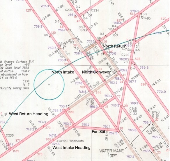
The North Conveyor Mk2B Roadheader at 194mmarkin 1985.
When the North Conveyor heading had progressed 700m in Feb 1985 a large junction was created. The Mk2B roadheader then continued on to the north of the mine. At the same 700m point in the North Intake heading in Feb 1986, a junction was created and the cross slit was created between the North Conveyor and North Intake roadways. At the North Intake junction, an heading was started, to develop the coal at the west of the mine. When the heading had progressed 100m a further junction was created. The machine turned right to create a 70 metre cross slit for the West Return and West Intake stub headings. The machine then drove an heading back towards the North Intake at 45° to create a ventilation slit for the heading fans and loco access. This development was phase two of Riccall Mine, to access the coal at the west of the mine up to the boundary with Wistow Mine.
In October 1986, the North Return and North Conveyor lateral roadways were completed. The South Conveyor was completed and the Return was well advanced. Both North and South Intakes were half completed and face developments were also started on both sides of the mine. This was the first phase of the development of the mine.
The West Development Headings.
In Nov 1988 the west development headings were started by mining contractors, Thyssens. The machines used for the West Conveyor heading was a Dosco Mk2B roadheader and West Return headings was a Dosco MK2A revised hydraulics roadheader. The headings were supplied by two Becorit battery locos owned by Thyssens. These locos moved equipment from a transhipment point at the bottom of the West Conveyor roadway.
Before the West Return lateral heading started, the West Return connection roadway, to the North Return, had to be completed. It was a 1 in 17 drift changing to a 1 in 5, driving above the North Intake and North Conveyor roadways. The connection, a 1 in 1 Drift, was created upwards from the North Return, using bore and fire with a slusher to muck out, to complete the heading. This drift was called Zolly’s Drift after the Thyssens general foreman. This allowed the West Return air to travel to the upcast No2 shaft.
The West lateral headings progressed and made junctions for H471s and H472s faces. The West faces were to be taken off the West Return retreating in a north to south direction. The first face to be developed was H472s. These headings were driven by Thyssens using Lee Norse LN800 2.5tt continuous miners and were supported using arch girders.
H472 Face and South West Trunk.
H472s face development gates were started in March 1990 and the 700m face headings, including 230m faceline, were completed in Oct 1990.
The cross slit between the West Return and Conveyor Road was completed and the west side 6.6kv ring main MIVAC substation was built in the slit, at a later date, to supply all the 8 west faces and and headings. A roadway was taken off the West Conveyor called the South West Trunk.
H472s coal face was the first one at Riccall Mine to have a Joy shearer. The first Joy shearer used in the country was at Manton Colliery on 39s face. It was a 3LS and proved very successful. At the time H472 was to be installed, 2 shearers were made available for Riccall Mine. A Joy 4LS and the ex Manton Colliery, Joy 3LS. It was decided that Riccall Mine had the Joy 3LS and Trentham Colliery got a new Joy 4LS. The 485kw, 3LS installed at Manton Colliery and then Riccall Mine, was the only one ever used in the U.K. and is now on display at the National Coal Mining Museum.
Joy 3LS Shearer cutters
The Joy 3LS was a brilliant coal cutter. It was a very powerful multi motor shearer capable of unbelievable cutting speeds. The combined horsepower of the machine was over 600 horsepower with each of the two cutter motors rated at 250 horsepower. The hydraulic onboard pump, and the D.C. traction haulage motors were a combined rating of 100 horsepower. The hydraulic pump was used purely for moving the ranger arm rams.
Shearer D.C. drive unit.
The 2×35 Horsepower D.C. traction motors were thyristor controlled with speed control set using a programmable electronic module. The traction drives operated a gear which sat on a huge captivated chain to haul the shearer through the face. We were told that when used in the American mines, where the face workers didn’t work on the tailgate (dusty) side of the shearer, the machine could cut at 60 feet per minute. We had stricter dust regulations in the UK so these speeds were restricted. The shearer driver operated the machine using a remote control powered from his lamp battery via a lead.
Shearer control panels.
The machine had a control section with an LED diagnostic panel situated in the middle section which was useful for fault finding. The cutter drums on the shearer was so designed that if it struck a solid object such as a chock beam, the output shaft from the ranger arm, to the cutter, sheared to ensure no damage to the gears of the ranger arm occurred. It was called a quill shaft.
H472s face was developed, as mentioned earlier, using Lee Norse continuous miners using arch supports. It was ready to start production in Jan 1991. The main gate pantechnicon was rail mounted and the face equipment was Gullick Dobson transferred from the northside of the mine. The face was very successful, finishing production in June 1991.
H472s face team with methane borers.
All faces at Riccall Mine had the entire electrical equipment, including transformers, returned to the surface, on every face, for a complete overhaul, redesign and testing. As the electrical equipment evolved, due to electrical developments, plug and socket connections were fitted, where allowed, for ease of salvage and installation.
West side faces from H470s
West side faces from H472s showing South West Trunk development.
West side faces from H474s H477S.
Lee Norse LN 800 continuous miners were used for all the West Side face headings with high rates of developments achieved due to the seam section becoming thicker as the mine progressed westward and the introduction of total bolting as the primary support system. The last 3 faces at the west of the mine were supplied with face equipment from the newly formed mining company, Longwall International, a merger of Meco International and Dobson in Jan 1993.
As the West lateral developments progressed the conveyor system was changed due to the length of the drivages and the faces worked. The slit from the outbye end of the conveyor road to the steel cord had a Huwood double drive which delivered onto the steel cord conveyor. A further Huwood double drive was installed just inbye of H472s slit supplied by an Wallacetown H65 installed on a large purdy platform outbye of H472s.The platform had to be built with sufficient height to allow men to walk underneath so we built the switchgear on the platform and then lifted the entire platform as high as possible. The conveyor became a manrider except for a short section at H472s junction where the South West Trunk delivered on the West Conveyor.
West Conveyor Manrider
West Conveyor Outbye
H477s Maingate end
The face taken from the inbye end of the West Return was H477s with a seam section over 3m and the chocks working on there limit. The equipment was then transferred to H478s which was a face developed on the West Side of the South West Trunk roadway. The next two faces taken off the West Return were H471s with 1000m gates and H470s with 550m gates. These faces used the equipment from H478s and were very successful faces both completed by Feb 1998.
Photo above shows the H471s face team in mid 1997. The lads shown are top row, left to right; Steve Priestley (Tiger), Andy Lister and Bob Yorke. Middle row, right to left; Ian Liptrot, Eddie Jordan and Steve Commons (Old hand). Front row, left to right; Roy Minett, Paul Morton (Pinky), Willie Baxter and Paul Ward. The photo has been kindly given to me by Ian Liptrot who has a copy from the RJB News magazine. It is taken at the main gate entry to the face.
The last two faces worked on the west side of Riccall Mine were developed from the West Conveyor roadway. These were very short faces to remove the final couple of blocks of coal at the west side of the mine. H434A’s development was started in September 1997. The Main Gate was driven with a Dosco MD1100, a 34 Tonne, 157 kw, medium sized roadheading machine.
Dosco MD1100 Roadheader.
West side H434A’s and H434B’s face plans.
H434A’s tail gate was driven along with the face line heading and then abandoned on 20 Feb 1998. In June 1999 the heading was de-gassed and development was restarted to complete the main gate roadway back towards the West Conveyor roadway. The heading was completed in September 1999. The face, which had 400m gates and a face length of 180m was installed and started production in January 2000 using a Joy 3LS Shearer with Joy face equipment and standard Wallacetown SIMOS 1100v electrical equipment. The face finished production in 12 weeks on 29th March 2000.
H434B’s started development on 20th Nov 2000. The face headings were completed in the same way as H434A’s in one complete development starting with tail gate, faceline then main gate using a Dosco MD1100 and was completed on 23rd May 2001. The equipment from H434A’s was installed and production started on 13th August 2001. The face was 200m long with 500m gate roads and took 3 month to complete production, finishing on 23rd Nov 2001. This was the very last face at the west side of Riccall Mine.
All the West faces had outstanding production figures, producing millions of tonnes due to the outstanding workforce, face conditions, seam section and Gullick Dobson / Longwall international face equipment, including the brilliant Joy 3LS shearer mentioned earlier, which was used on most of the West side faces from 1990 until 2001.
Many thanks to Ian Liptrot, who was an electrician at Riccall Mine, for information on H434s faces and the great photo of H471s team.
Many thanks to Kevin Grant for information about the Thyssens developments.
When Riccall Mine closed as a producing mine in October 2004 many changes had to happen on the surface and its buildings to change the use of the site. When the Selby Coalfield was conceived and planned, the surface infrastructure was planned to be demolished and returned back to farming land but this did not happen. UK Coal persuaded the the planning authorities that the 104 acre site could be used as a multi use, mixed industrial, warehouse and office space after specific areas and buildings were demolished and made safe.
Harworth Estates acquired the site from UK Coal during the transition period in the coal industry and the A19 Business Park was created on the site.
Entrance from old car park
Probably the biggest task on a closed mine site was to make the mine entrances safe. The next major job was to demolish and clear the winder towers and winders.
After discussions, UK Coal persuaded, the then Coal Authority, that due to the high engineering standard and strength of the Selby Coalfield mine shafts that the integrity would ensure the shafts would last 150 years. This meant that the shafts did not need to be filled, at great expense, but a heavily engineered cap in each of the shafts, small plug and further cap on the surface would make the shaft entry secure.
The first task was to remove all power and communication cables, pipes, winder ropes and guide ropes to ensure the integrity and strength of the seal into the shaft wall. In the case at Riccall Mine, all the above mentioned items were cleared to a level below the area in the shafts below the air drift entrance at the No1 downcast shaft and the fan drift at No2 upcast shaft. The 24 ft diameter shaft had pockets (holes) cut into the concrete of the shaft wall at various points. This was a very difficult job due to the incredible strength of the concrete shaft linings used at Riccall. Large girders were installed across the shaft and fitted into these pockets and bolted together with other jointing pieces to create a huge, high strength lattice work for the steel cap base to sit on.
Once the steel cap was installed, the shaft air drifts and shaft tops were filled with a clean limestone aggregate and poured concrete to a point just below surface level. The final stage was to create a concrete shaft top cap over the infill.
No1 downcast shaft cap
No2 upcast shaft cap
The No1 winding tower, No1 winding house, No2 koepe winder and fan house, shown above, were all demolished, using heavy duty equipment, due to the heavily engineered structures, once the caps were fitted on the shafts. The methane plant to the right of the fan house was also decommissioned and the equipment removed.
Theentrance to lamproom from No1 shaft.
The photo above shows where the covered area to the No1 shaft top was. It was a large tiled area with bottle filling and cleaning facilities.
The view looking from the pit lane into the pit yard with store building on the right.
The view above shows the store building on the right and the fluidised bed boiler house on the left. In the early 1990s Riccall Mine started using a generator supplied by Dale Engineering. The generator was supplied via the mine’s methane drainage system from the coal faces. The system had to have a filtration unit to remove any dust picked up from the piping of the methane from the face to the surface. The site of the generator is shown below.
View looking onto methane drainage house and generator site.
The view across the pit yard looking onto the electrical workshop, cable store and the mechanical workshop. The stockyard was a huge area to the right of the photo.
The view across the pit yard from the shaftsmens workshop looking onto the mechanical workshop, workshop offices and electrical / cable workshops.
The view from No1 shaft entrance looking at the electrical substation, the site of the No1 winding house and shaftsmens workshop. The No1 shaft cap is on the right.
When you walk around the surface at a closed mine you always remember how busy it was. It is a sad sight and so very quiet. When it was a working mine, men and machinery were moving around at all times of the day and night with the associated noises of fans, winders, moving mine cars and shifts of men chattering at certain times of the day. A sad end to it all.
Information about shaft remediation kindly provided by Dave Scott, a mate who worked at Glasshoughton Colliery, Wistow Mine and Kellingley Colliery.
When the develoment of the Riccall Mine surface started the site was basically part of a disused WW2 airfield last used in 1958. The site was 64 acres of the RAF Riccall satellite station, the rest of the base is now part of Skipwith Common National Nature Reserve.
The first thing to do was clear the site and prepare the shafts for sinking. The shafts in the Selby Complex used a brine solution system to freeze the water bearing strata to enable sinking to take place through the water, rock and ice.
The shaft sinking contractors used at Selby were Cementation Mining Ltd who sank Wistow, Riccall and North Selby mines. Thyssen Mining (UK) sank Stillingfleet and Whitemoor mines. The water bearing strata in the Riccall shafts were frozen to a depth of 253m. To achieve the frozen zone, boreholes were drilled at uniform distances around the circumference of each shaft to 255 metres. Pipes were entered into the boreholes and filled with a saline solution. The pipes were connected to a compressor and the freezing process was started. When the freezing process was completed a thirty foot plug of ice was created around the shaft. Once the frozen zone is achieved around the shaft circumference sinking can start.
As the groundworks for the shaft tops were prepared lots of equipment was moved onto site to support the sinking operations.
A concrete preparation plant was installed onsite due to the immense quantities needed for not only the shafts but building bases, surface buildings, ductings and fan house ventilation airways.
The shaft sinking in the first thirty metres of the two shafts had major differences in design. Number one shaft was a downcast shaft, with a ventilation intake drift on the East side of the shaft. This was incorporated into the shaft design and was part of the concrete shaft wall just below the surface. The ventilation drift had a shaft heater system but was never used.
Number two shaft was an upcast shaft. The shaft design at the surface incorporated a fan drift connected to the two main 2100kw ventilation fans to the east of the shaft via two smooth concrete tunnels.
The shafts were sunk using drill and blast and progressed well through the water bearing strata. Once the initial surface sections were completed the sinking winders and associated equipment needed to sink the shafts were installed.
Each shaft had a 5 deck sinking stage suspended in the shaft to carry out the various processes involved. This sinking stage had 4 synchronised winches to lift and lower the stage. The processes involved in the sinking were the drilling of the shaft bottom, blasting and mucking out. The shaft walls had to be drilled, bolted and meshed. Two metre long shutters were put in place around the shaft and concrete was poured into the void between the shutters and the shaft wall to line the shaft. The shaft concrete lining was one metre thick. Water resistant seals were fitted in the shaft lining in certain areas of the shaft sinking. In the middle of the sinking stage was an access hole for the cactus grab and kibble used for removing the shaft muck to the surface. When the sinking stage was lifted and lowered, a communication and power cable was also lifted and lowered. As the shaft was sunk concrete pouring pipes, compressed air and water pipes were installed.
Shaft sinking winder.
Any period when men were working in the shaft, doors were placed on the access to the shaft to ensure no equipment or debris fell into the shaft.
This photo shows the Cactus Grab, for mucking out, man riding kibble, meshing and strap basket. Air, water and concrete pipes are shown ready for installation in the shaft. The shaft doors are shown in the up position.
During the sinking process the mining engineers had to overcome some problems. The solutions were planned and designed into the sinking process. One of these problems was the Basal Permian Sands which had a water pressure relief system installed. This involved leaving a two metre gap in the shaft concrete lining to ensure the relief system worked and seals were installed but allowing the shaft sinking to progress. When the process was proven to work the shaft lining was completed.
Photo shows Neil Rowley on the top sinking stage at 629m depth in the shaft inspecting the basal permian sand water relief system prior to shaft lining. The shutterings and seals are visible. The shaft lining is one metre thick, sulphate resisting concrete. The concrete linings at Riccall and North Selby Mines were increased in strength due to strata hydrostatic pressures.
Photo shows temporary headgears with No1 permanent winding house built and air inlet shaft. The concrete batching plant is shown between the temporary headgears.
Photo shows fan drift to fan house under construction. The building housed two 2200kw axial flow, variable pitch fans.
Fan drift showing ventilation fans.
As the shaft sinking progressed the surface buildings and infrastructure were built simultaneously. The permanent shaft headgear was built at the side of the temporary equipment and were moved into position when sinking finished.
Photo shows permanent headgear to the right, sinking headgear on the left.
When completed in September 1983 the shaft depths were 792m at No1 shaft and 805m at No2 shaft set at 100m centres and 7.315m diameter.
Riccall Mine No1 shaft Mine car handling plant.
Riccall Mine No1 pit bottom mine car handling plant.
Car park looking at pit yard during construction.
The photograph below shows Riccall Mine when all temporary equipment was removed and all the surface buildings were fully operational. When completed the mine was barely visible from the road having used the extracted material from the shaft sinking and soil to create a natural banking around the site. The winding headgears were also designed to be shorter in height than conventional towers.
Many thanks and kind regards to Neil Rowley, an Undermanager at Riccall Mine during the development of the mine and Deputy Manager at Gascoigne Wood mine for providing photographs and information in this post.
Introduction: The first two faces at Riccall Mine were HO2DRs known as D2s and HO1CRs known as C1s. They started production in January 1988. The ‘C’ coal faces were at the south side of the mine. The ‘D’ coal faces were at the north of the mine. The first eight coal faces were all developed from the north and south return roadways, retreating from east to west with the seam dipping to the east. During the development and subsequent installation of D2s face a huge, simultaneous work program was underway to install the coal clearance system to Gascoigne Wood Mine.
The first north side face, HO2DRs.
The first face at the north of the mine was D2s. This face was around 900m from the pit bottom and had a face length of 200m. The Tailgate was developed using a Lee Norse LN800 1TT continuous miner. This machine was an american specification machine, the first of it’s kind in the UK. The machine had 120v control circuits unlike UK machines which had intrinsically safe, pilot voltage, control circuits. The machine had to be modified to pilot control to operate from UK Gate End Boxes before it was accepted into a UK coal mine. All electricians who worked on this machine had to complete a two day training course before working on the machine. This heading was the first development at Riccall Mine to trial roof bolting as a supplementary support so was monitored very closely. The machine was extremely powerful and would cut out in less than 10 minutes. The gate length was 1600m with the machine also cutting the face line. The face was at a depth of 850m from the surface.
H403s maingate Lee Norse LN800 Continuous Miner
The Main Gate was developed using a Dosco MK2a Roadheader Revised Hydraulics. The supports were identical to the ones used on C1s face with a Cruciform leg, on the face side, for extra support when the shearer cut into the main gate. The main gate progressed really well due to the amount of coal in the face of the heading which made cutting easier. Both C1s and D2s were supplied with equipment using Clayton BoBo battery locomotives.
The main difference between the north faces and south faces were the face equipment manufacturer. The A.F.C., stageloader, crusher / sizer, coal face shield supports and powerpack pumps and tank were supplied by Gullick Dobson. The face supports had chock interface units which could be set to advance the A.F.C. and face supports automatically in zones or by shearer initiation and were lit throughout. Both the north and the south faces used Davis Derby signalling and audio systems, with a SIVAD A.F.C. and stageloader control and monitoring unit mounted on the main gate pantech. The face signal and audio system cables had camlock cable entries for easier fault finding.
The shearer was an Anderson Strathclyde AM500 DERDs
Between the Stageloader drive head and the pantech was a Hausherr Dinting Machine. This gave the roadway in front of the stageloader delivery sufficient height to move whilst retreating.
The pantechnicon with the face electrical switchgear, cables, pumps, tanks and transformers was identical to C1s face which was monorail mounted. The double acting ram used for moving the equipment out whilst the face retreated, was rated at 85 tonnes and was mounted at the outbye end of the Pantech. As the pantech moved outbye on the monorail, the 6.6kv 631 pliable wire armoured cable also mounted on the monorail, bunched up creating figure eights. When the face had retreated 95m the Wallacetown M82 face isolator was moved outbye 100m and the 631 cable was pulled out straight allowing the face to retreat another 100m.
This face, due to gate length, had a tandem conveyor. The main gate end had the same overband magnet as C1s, removing any metal debris before delivering the coal onto the steel cord conveyor.
D2s was a success along with C1s and continued producing well until 100M from the finish mark where a sandstone intrusion fault 30m from the main gate end, stopped the face. Huge sandstone lumps were causing severe problems in the fault area with one falling onto the ranging arm and lifting the 60 tonne shearer off the haulage rack unit. Boring and firing was used for a few days but due to the shearer being unable to cut the sandstone through the fault and very dangerous face conditions the face had to be stopped early on 19th December 1988.
The next face to start production at the north side of the mine was H403s. This face was a carbon copy of D2s in face and gate length. The main gate was developed using the ex D2s tailgate Lee Norse LN800 1TT Continuous miner with the tailgate driven with a new JCM 12 Continuous Miner. Both gates were supported using arches.
Due to problems with soft roof on the Riccall coal faces mentioned in another post and the base lifter ram modification to the face supports, D3s(H403s) was installed with an new, modified Gullick face kit and shearer. This face had a AM 500 DERDS Selectronic M.I.D.A.S. shearer designed to overcome the friable roof.
The M.I.D.A.S.( Machine Information Display and Automation System) had been trialled at Wath Main and Silverwood Collieries on single ended shearers and was designed for automatic steering of the shearer. When installed, the shearer transmitted data to the surface control room, via the mine transmission system using a new type of trailing cable called a type 7S, with transmission cores, to relay the data to the main gate and then to the surface.
Using the onboard system called a Machine Automation Digital Display(M.A.D.D.) , the shearer had parameters set, including seam section, face length and amount of coal top to be left. During cutting, the machine had a roof follower arm mounted on top of the shearer ranging arm touching the top of the seam. As the shearer progressed through the face, the follower arm gathered data on the coal seam undulations from a unit mounted at the base of the follower arm, transmitting it to the M.A.D.D. unit. At the end of the cut, an end of face detector sent a signal to the M.A.D.D. unit to save the last cut information, along with data gathered from inclinometers on the shearer called Face Advance Tilt(F.A.T) which measuring face advance angle of the seam. On the return cut the shearer, using the last cut data and automatically steered the ranging arm, using solenoid operation of the machine to control the operation. The shearer also had servo operated control of the shearer speed with a push button and electronic speed controller called a PB8 End Station. The shearer on D3s was a double ended shearer so the electronic control system was modified to operate and gather data whilst cutting coal. The data was then used to control the two cutting drum on the return strip of coal.
The pumps and tanks were identical to D2s and were monorail mounted. The only difference was the electrical gate end boxes, which were the ex C1s Wallacetown S.I.M.O.S. equipment. The face started on 3rd January 1989. The face performed OK due to the M.I.D.A.S. shearer overcoming the weak roof, but had it’s problems in certain areas and took 12 months to complete finishing on 17th January 1990.
The D3s face team with the M.I.D.A.S. shearer expert, shift charge engineer, Dave Greenwell.
The next face to be developed was H404s using 2 x Lee Norse LN800 2tt continuous miners. Once the LN 800 machines were proven, they were the mainstay for all the Riccall Mine face developments. The Lee Norse machines at Riccall used a specially developed, heavy duty, bridge conveyor bolted to the tail delivery which had a Lioness drive to clear the coal. The conveyor was wider than a standard bridge conveyor and could clear the coal very quickly. The heading machine cable handler was a Purdy monorail system which had a double runner system. This was in effect 2 monorails welded together. The machine cable moved in the lower rollers whilst the entire monorail could be moved forward on the roof mounted top rollers. This way only the roof mounting brackets, with runners needed moving forward. Both H404s headings, which were 1100m, were supported using roof bolts as the primary supports.
Riccall Mine north side faces.
H404s main gate was a different face design to H403s as it had a floor mounted pantechnicon with remote chock pumps. The electrical switchgear was Baldwin and Francis B.F.S. It was designed to be installed as part of the stage loader so was inline with the conveyor. It was a complete nightmare to install and maintain due to the sliding platform access for the switchgear, and the type 201b cables running over the top, in the very tight gap. A few fingers and hands were trapped during the installation. The transformers were rail mounted on skids with a monorail system to transfer the cable supplies into the switchgear.
The automated, remote, face support power packs were installed at the main gate end. The pressure supplies to the face were supplied through high pressure, threaded flanged jointed, pressurised pipes. The flexible hoses to the face were connected through a valve bank for isolation purposes at the face. This was the only time this system was ever used at Riccall Mine.
The shearer was an identical AM 500 DERDS Selectronic M.I.D.A.S. shearer used on H403.
The longer, 230m face started in February 1990 and due to the advanced technology of the shearer progressed in some very heavy face conditions. The face finished 50m early in October 1991 due to a washout. The face was salvaged quickly and re-installed on H406s.
H404s tailgateat 760m mark
The next face was H405s, which used the ex H404s, Lee Norse LN800 continuous miners to develop the face gate headings. The bolted headings progressed quickly with the face ready for installation in late 1991. The face supports, power pack pumps and tanks were Gullick Dobson, with the power packs and tanks installed at the face. The main gate electrical equipment was the overhauled, ex H403s, but totally re-designed to be rail mounted. All faces installed after Jan 1991 were rail mounted pantechnicons due to the face headings using total roof bolting as the support system.
The 250m long, H405s face performed well and finished production in April 1992.
The next face to start production was H406s which was the only face taken off the North Intake nearly opposite H405s. This face was a 200m face with 700m gate roadways and had identical equipment to H405s, except the shearer which was a standard AM 500 DERDS . The face started production in Jan 1992 and finished in July 1992. When the faces at the north of the mine were completed the Gullick Dobson face equipment and 2 of the LN 800 continuous miners were used at the west of the mine.
In 1992, Riccall Mine was the first one of the Selby Mines to produce over 2 million tonnes producing 2,200,000 million tonnes. In 1993 Riccall Mine produced 2,600,000 million tonnes of coal. In 1994 Riccall Mine produced 3,060,000 tonnes of coal. These outstanding figures were produced from 12 longwall coalfaces. Two faces were at the north of the mine, 4 faces were at the west of the mine, two faces were at the east of the mine and 3 faces were at the south west of the mine.
When the main drivages at Riccall Mine were completed and the connection to Whitemoor Mine was made at the South Conveyor Roadway in December 1986, the job of creating a coal clearance system for both mines was started. One of the first jobs in early 1987 was to make a connection with Gascoigne Wood to allow men to travel to work at the furthest point of the Gascoigne Spine tunnels. Amco were given the job of sinking a 66.2m, 1.2m diameter inclined access borehole.
The incline shaft to Gascoigne Wood.
This was sunk at the far north of the mine between the ends of the North Return and North Conveyor Roadways. The initial shaft was bored from Riccall Mine to Gascoigne Wood. A larger bore was made by pulling the shaft borer back up the shaft from Gascoigne Wood to Riccall. A ladder access was then installed. This allowed access for the Amco contractors to work on the two staple shafts, called Bunker 7 and Bunker 8. The bunkers were 57m in depth and 7.5m in diameter and were designed to allow 2000 tonnes of storage of coal if there was a problem with the Gascoigne Wood coal clearance conveyors.
During the final 9 months of the Robbins TBM South Spine drivage, bad ground was encountered and the drivage slowed up considerably. A decision was made to drive an heading West from Riccall towards Stillingfleet and make a further connection until the Robbins TBM South Spine was completed. This was called The Stillingfleet Connection.
Riccall Mine bunker area.
The heading machine used to drive the Stillingfleet Connection was the ex North Return MK2B Roadheader with FSVs supplying the heading. This heading was driven but was never used for it’s original purpose of coal clearance. The conditions improved in the Robbins TBM heading and it was successfully completed.
The North Conveyor Roadway Bunker, Conveyor Drivehouse and Bunker area had to be created.
The North Conveyor MK2B Roadheader was tracked back from the furthest point north to a point 100m from the new planned drivehouse. The Roadheader then recut the roadway, widening in the drivehouse area, dinting the roadway and setting large, square section girders for 300m. The Roadheader was tracked back again to the start of the square work. A setting platform, on monorail was created. The Roadheader then dinted approximately 2m of roadway, replacing the girders legs as it moved forward, creating a huge roadway section through the Drive House and Roadway Bunker up to the site of the Bunker 8 Staple Shaft. The Drive House was dinted again with a Dosco Dintheader to allow for the dimensions of the Steel Cord Conveyor Drive to be built.
Dosco Dintheader.
The final size of the drivehouse was 8m high by 80m in length square section roadway.
The Riccall Steel Cord Conveyor, one of six installed in the Selby Complex, was a very powerful Conveyor capable of moving 2000 tonnes per hour. The installation was designed and commissioned by Huwood Mining. OMEC Mining were contracted to build the gear head and Conveyor with it’s associated structure. The structure was built from various points of the North and South Conveyor Road where loco access was available. The conveyor was installed in 300m lengths each weighing 14.5 tonnes and were 1.35m wide and 17.3mm thick. For the purpose of installation and maintenance, purpose designed lifting, handling and vulcanising facilities were installed and were situated in the No2 shaft pit bottom area. The return end was at the Whitemoor Bunker Connection.
The Riccall Conveyor Drivehead was a double drive operated by two modified 6.6kv NEI Peebles HF2VG in sequence. It had scoop trim fluid couplings with acceleration control operated by modified KLS lighting and signal transformer units called Scoop Trim Panels. The coupling scoops were controlled by electrohydraulic actuators. Each motor was rated at 750 kw (1000 Horsepower).
When the huge square section Bunker Roadway at the end of the Riccall Steel Cord Conveyor was finished the job of creating a coal storage and clearance system was started.
A twin inboard AFC was installed in the bunker roadway underneath the conveyor which ran the length of the bunker. A BJD Maximatic shearer with a large scrolling drum was mounted on the panzer. A suspended walkway was built in the top of the bunker with a remote control system to operate the Coal Reclaim Shearer. A traversing plough delivery was installed on the Conveyor to be used if a problem occurred at Gascoigne Wood. This ploughed the coal from the conveyor onto the bunker floor. When Gascoigne Wood Coal Clearance re started the coal was loaded back onto the panzer which loaded back onto the Conveyor to be loaded into Bunker 8.
At the Steel Cord delivery end a control point called The Wendy Box was created. This was staffed and all the production passed through this point. The production could be directed onto the Bunker Conveyor directly to the Staple Bunker 8 into Gascoigne Wood, ploughed into the bunker for reclaiming later or directed to the North Intake Conveyor via a Westerland Weigh Feeder Conveyor, a conveyor containing load cell modules to weigh the coal passing through the system to be sent to Staple Bunker 7 into Gascoigne Wood. All production was controlled via a control panel with information from Gascoigne Wood Control.
Introduction: The first two faces at Riccall Mine were HO2DRs known as D2s and HO1CRs known as C1s. They started production in January 1988. The ‘C’ coal faces were at the south side of the mine. The ‘D’ coal faces were at the north of the mine. The first eight coal faces were all developed from the north and south return roadways, retreating from east to west with the seam dipping to the east.
Face Team. Photograph courtesy of Dave Greenwell
The first south side face, HO1CRs
The first face at the south of the mine was C1s. This face was around 700m from the pit bottom and had a face length of 150m working at 800m from the surface with a gate length of 800m. The Main Gate roadway was developed using a Dosco Roadheader MK 2a Revised Hydraulics. The roadway was driven using supports I had seen at South Kirkby Colliery with a face side support leg called a Cruciform. Each setting had extra braces welded on to the part of the face side of the crown of the support. This enabled extra support steel to be bolted between each girder, rather like a heavy duty strut, but the same size as the support. This type of support allowed the face workers in the main gate to remove the leg of the support whilst keeping the extra support brace in place to maintain integrity when the shearer was cutting into the main gate.
The face supports on C1s were Dowty 4 X 700 tonne shield supports. The supports had a coal interface unit in each chock, with the ability for automated A.F.C. and support advancement and shearer initiation which was never used on this face.
During the first few weeks of production it was realised that the supports were difficult to keep level due to the front of the supports digging in when advancing due to soft floor. This was subsequently rectified by fitting base lifter rams on the front of the chock. This lifted the leading edge of the chock base by acting on the relay bar as the chock advanced.
The face was lit throughout using the Dowlite system of intrinsically safe, high frequency lights. The transformer units were designed by Status.
Dowlites.
The armoured face conveyor was a twin inboard 28mm chain, powered by two, 2 speed motors of 150/300 kw. The panzer was a side discharge onto the Stageloader, the first I had ever seen.
Original photographs on the Dowty Archive at the Gloucestershire Heritage Hub.
The shearer was an Anderson Strathclyde AM500 Double Ended Ranging Drum Shearer power loader for cutting the coal.
C1s AM500 DERD Shearer. Okker Armitage and Gary Pollitt were the drivers.
The stage loader was 150 horsepower with an 150 horsepower, inline sizer/crusher. The face hydraulic system was supplied from 2x 150 horsepower powerpack pumps and a tank mounted on the pantech. The coalface equipment cables and hydraulic hoses were installed in a system called a Back to Back Bretby cable handler. This comprised of 4 sections of bretby approximately 50m in length, mounted on monorail, bolted together mounted top and bottom and side by side.
This allowed the cables and hoses to compact when the face retreated and extend when the Pantech was pulled out during production.
Between the Stageloader drive head and the Pantech was a Hausherr Dinting Machine. This gave the roadway in front of the Stageloader delivery sufficient height to move whilst retreating
The Main Gate coal clearance system was designed to be able to produce 1500 tonnes per hour. The slit onto the main steel cord conveyor had a powerful overband magnet to remove any steel fragments coming from the face conveyors. The electrical and hydraulic equipment supplying the coal face, known as the Pantech, was mounted on steel frames, hung on a monorail system from the roadway support girders. The Wallacetown A74, A74/9 Panzer GEBs and all the electrical equipment was powered by two, 1 MVA transformer supplied at 6,600v to 1,100v for the face equipment. They were supplied by a Wallacetown M82 face isolator through a 6.6kv type 631 pliable wired armour cable, mounted on monorail pivoting brackets, enabling the pantech transformers to be moved as the face retreated during production.
The Tail Gate of C1s was driven using a Joy Continuous Miner CM12 with two shuttle cars loading onto a conveyor. The shuttle cars were the first and last time they were used at Riccall Mine. Having 2 Shuttle Cars gave extra coal storage during cutting.
The second South side face, H02CRs
C1s face progressed well and production was as expected. The face headings for C2s were driven using a new Lee Norse Miner LN800 2TT in the tailgate and the ex C1s tailgate Joy CM 12 in the maingate. The headings were supplied with a new fleet of diesel free steered vehicles. The headings were driven using arch supports.
LN800 2TT Continuous Miner
The face roadways on C2s were 1400m and once the face line was completed the heading machines were driven out of the Tailgate and around to the new face headings, now designated as H443s.
When C1s face was nearing the finish point in June 1988 the face was prepared for salvage. Rolls of plastic mesh with straps and roof bolts were installed in the front of the face after each strip of coal. The supports were advanced and the meshed roof passed over the supports and eventually into the gob at the back of the face when enough cuts of coal were taken. When the gob at the back of the supports, the roof above the supports and the face front were fully bolted, meshed and strapped the face supports were ready to be withdrawn along with the AFC. The face finished on 14th June 1988.
Face meshed and bolted for salvage.
The AFC was split into sections of 3 pans and withdrawn along with the supports. They were transferred using a Gullick Dobson MP150 free steered vehicle to C2s faceline to be reinstalled. As the chocks were withdrawn, the face had secondary concrete block support chocks installed.
F.S.V. hauling coal face support
Once the face salvage bolting cuts were completed and all coal cutting had ceased the stage loader, crusher / sizer and cable troughs were transferred and built up in the new C2s maingate.
The face hydraulic pumps, tanks, electrical gear, cables and transformers were brand new so were transported from the surface, already built on the Pantechnicon sections. C2s face trialled a new set of electrical gate end boxes to supply the face machinery called S.I.M.O.S., manufactured by Wallacetown Engineering. The panels were a new, microprocessor operated, vacuum contactor. The Pantech set up was identical to C1s, so everything was monorail mounted. C2s face started on 13 July 1988
Due to design upgrades, the S.I.M.O.S. switchgear were all replaced with updated versions at a later date. This job involved two very long weekend shifts to get it done before starting cutting again on monday dayshift.
The plan below shows the four faces at the south side of the mine showing the depth of the Barnsley seam with start and finish dates. The green line at the top left shows the shaft pillar, an area around the shaft where coal cannot be mined to protect the shaft from subsidence.
C2s coal face progressed well but the soft top of the coal seam was a cause for concern on both C2s and D2s faces. C2s face finished on 7th April 1989 and all the face equipment was transferred to the new face, now called H443s, with the addition of extra face supports due to the face length being 200m. The only changes to the electrical equipment, pumps, tanks and transformers supplying the face was the Wallacetown S.I.M.O.S. gate end boxes supplying the face electrical equipment were replaced with a new switchgear called Baldwin and Francis B.F.S. The face started production on 8th June 1989.
During the development of H443s main and tailgates, a partial washout was encountered at 850m mark in the roadway. The headings progressed to 1600m and the face was installed at that point. Anderson Strathclyde AM500 DERDS shearer were used on C1s and C2s. An Anderson Mavor AM500 Selectronic M.I.D.A.S DERDS was used for the initial face installation on H443s but was replaced with two single ended AM500 Selectronic M.I.D.A.S. shearers for the re installation of H443s. The original shearer was overhauled and used on H404s face.
The M.I.D.A.S.( Machine Information Display and Automation System) had been trialled at Wath Main and Silverwood Collieries on single ended shearers and was designed for automatic steering of the shearer. When installed, the shearer transmitted data to the surface control room via the mine transmission system via a new type of trailing cable called a type 7S with transmission cores, to relay the data to the main gate and then to the surface.
Using the onboard system called a Machine Automation Digital Display(M.A.D.D.) , the shearer had parameters set, including seam section, face length and amount of coal top to be left. During cutting, the machine had a roof follower arm mounted on top of the shearer ranging arm touching the top of the seam. As the shearer progressed through the face, the follower arm gathered data on the coal seam undulations from a unit mounted at the base of the follower arm, transmitting it to the M.A.D.D. unit. At the end of the cut, an end of face detector sent a signal to the M.A.D.D. unit to save the last cut information, along with data gathered from inclinometers on the shearer called Face Advance Tilt(F.A.T) which measuring face advance angle of the seam. On the return cut the shearer, using the last cut data, automatically steered the ranging arm, using solenoid operation of the machine to control the operation. The shearer also had servo operated control of the shearer speed with a push button and electronic speed controller called a PB8 End Station.
When the face retreated to the partial washout on 11th October 1989, the face was salvaged and very quickly re-installed. The main gate electrical equipment was pulled out on the monorail system to the new face start position and face was cutting again on 7th November 1989.
On the 7th December, a visit by Queen Elizabeth and Prince Phillip was planned. The face was prepared for the visit with cover plates fitted over the pan side cable and hose brackets to ensure no accidents happened during the visit. A roof bolting demonstration and a demonstration of the shearer cutting coal was planned. During the visit only a skeleton staff were allowed underground. I remember that three electricians, from our team, were at strategic points to ensure electrical problems were quickly dealt with, one being in the pit bottom substation, one at the main gate end substation and myself on the face. When it came to the visit day Queen Elizabeth was ill so the visit went ahead with Prince Phillip attending. I was waiting in the tailgate when I got a call to say that the face A.F.C. would not start. A very concerned undermanager appeared in the tailgate to ask me to go and see what was wrong. I quickly went to the maingate to see what the problem was. A power supply fuse had blown In the BFS switchgear supplying the panzer and it would not start. I replaced the fuse quickly and thankfully the A.F.C. started. The visit went ahead as planned with no further problems.
Checks given to the men at Riccall Mine after the Royal visit.
H443s completed production slightly earlier than planned on 23 May 1990 due to a small washout fault in the tailgate and the equipment was transferred to H444s, the last face at the South side off the South Return roadway. This unit was a 250m long face with 800m face gates. and started production on 3rd July 1990. The single ended shearers were replace with an AM500 Selectronic M.I.D.A.S. D.E.R.D. shearer. All the other face equipment was transferred. All the electrical equipment was replaced with overhauled equipment, including transformers. The face was completed in 6 months, finishing production in Dec 1990. The face equipment was returned to the surface for overhaul by Meco International, to be re used on the faces at the east of the mine.
This is a little bit of my history and memories working as a Part time Mines Rescue Brigadesman at the Selby Coalfield.
I was a miner from 1979 when I started as an apprentice electrician at South Kirkby Colliery and I worked at 4 pits during my time as a miner. I have worked on the coal face and in headings (tunnelling) since 1980 aged 17. I always knew about what a Rescue Man did after talking with my Grandad Sep, who was a Rescue Man at Monckton Colliery at Royston and worked for the Rescue Corp retrieving casualties from collapsed buildings in the WW2. I also remember the Lofthouse Colliery Disaster and the Houghton Main Disaster as a young lad. One specific incident in 1983 where a good friend of mine was killed at my first pit, South Kirkby, made me want to join the rescue team. I was unable to become a Rescue Man at my first pit due to availability of spaces but was put on the list for training by my Colliery Overman, when a space came up. Due to the miners’ strike and subsequent colliery closures, this never happened. When I transferred to Riccall Mine, in the Selby Coalfield, I finally became a Part Time Rescue Man after being put forward by the Colliery Safety Officer, who was also one of the Rescue Team Captains. I did my initial 14 days training in early 1994 at Selby Rescue Station and became a member of the Riccall Mine Rescue Team.
How did you become a Rescue Man and what do you think a Mines Rescue Man did?
After acceptance of application and before initial training you had to pass a very thorough medical including eyesight, hearing, lung function, x-rays for lung dust damage, mobility and fitness test using a treadmill and heart monitoring. This medical happened every year whilst you were a Rescue Man. This was required due to regulations for wearing breathing apparatus. An interesting fact, from before my time as a rescue man, was you had to have teeth in good condition due to having to bite on a mouthpiece rather than using a facemask.
You had to pass a Mining First Aid Training course including administering Pethidine (Morphine) pain relief injections. You had to pass a Flame Safety Lamp gas testing course. You must learn how to feed canaries (only joking)
Initial Training. Initial training consisted of a rigorous 14-day course. During the course you had to prove competence wearing Breathing Apparatus in all types of mining, confined space and rescue scenarios.
S.E.F.A (image courtesy of Anthony Appleyard, at English Wikipedia)
The breathing apparatus used was called a S.E.F.A. which was an oxygen closed circuit (rebreather) type, designed to last 2 hours (+20%) in good conditions. In tougher conditions the Breathing Apparatus could be set to give higher Oxygen flow but only lasted 1 hour. It basically looks like a stainless-steel box with 2 vacuum cleaner pipes and a face mask. You had to learn how to use, charge, strip, clean and rebuild the set. You learned how to examine, test and maintain the set but mainly trust it with your life. This was done twice a day, every day, during your training. Wearing this equipment gave you terrible headaches for a few days before your body became accustomed to breathing 100% Oxygen. Included in the course was a wearing inside a hot and humid chamber where the trainees were tested to the limits of the breathing apparatus in extreme heat and humidity whilst carrying water barrels, cycling, shovelling hardcore, lifting weights and other high intensity exercises. The team captain monitored every team member with environmental conditions and oxygen gauges being checked and recorded. The heat and humidity were monitored using a piece of kit called a Whirling Hygrometer, which consisted of 2 thermometers on a frame. One had a wet sleeve over the thermometer bulb with the other one being dry. This equipment gave temperature and humidity recordings to decide the duration of working time. The time inside the chamber lasted 19 minutes, the maximum in these conditions. This was carried out as part of another training session, so we never had a steady day.
Casella Whirling Hygrometer. Photograph courtesy of the Science Museum
Let me tell you what a Rescue TeamCaptain did! Rescue Team Captain’s needed to be logical, quick thinking problem solvers. They were expected to have a good local knowledge, be highly trained and experienced. Being pragmatic, practical and courageous was also a great quality. One of the captain’s jobs before going down the pit was to check the lamproom barometer and log the reading. Low surface atmospheric pressure causes methane to migrate from the coal and the workings underground. This can elevate methane levels which is very dangerous. His job was to ensure the safety of his team so theoretically he would not carry out any practical work. He had to ensure the team had all the equipment needed before they went underground and that it had all been checked and ready to go. He had to check his team’s B.A.s before leaving the fresh air base and monitor the teams oxygen use by doing gauge checks every 15 minutes. He had to keep an eye on the team members to ensure they weren’t suffering ill effects. He had to log the teams progress into the mine, using his mine plan, marking the way in and out so that they could get back out without running out of oxygen. He made a written a log of everything they did and marked anything relevant on the mine plan. He was the one who lead the team so he gave the signals, by whistle, to control the team movements. He ensured environmental readings were taken to ensure safety of his team and this information was passed on to the next team at the fresh air base. He listened to his teams brief at the fresh air base very carefully and annotated it in his logbook with the task they needed to do.
Due to the Lofthouse Colliery Inrush Disaster in 1973, new training was needed involving using breathing apparatus in mine slurry and water. This involved working as a team in a swimming pool carrying weights to ensure you weren’t buoyant, whilst having a black out bag over your head and facemask. We had to walk around the pool in loops to feel what it was like trying to breath in your B.A. sets in the 10-foot-deep end of the pool. This was quite a difficult test due to the water pressure and It felt like trying to breathe with a wide, tight belt around your chest. Another training exercise involved using your Breathing Apparatus in a scenario where you were entrapped. We visited Kellingley Colliery for this training using some of the old mine workings to do it. The team captain, using a mine plan, had to find a specific point in the mine. Then we were told the roadway had collapsed behind us and the team was trapped. Your aim was to minimise your oxygen use to ensure it lasted as long as physically possible. This is achieved by turning the valve on and off and feeling for the carbon dioxide building up then restoring the oxygen flow. The team captain monitored everyone, with only one lamp being used, to ensure no one got into difficulty. Quite a responsibility you could say. We all survived thankfully. During the training we worked together as teams of 5, one of us carrying out the duties of Captain for that day. We used most of the equipment available for use in rescue work during the two weeks until it became second nature. First Aid was a major part of our training. It involved uses of 3 different types of stretchers and carrying sheets, including drag stretchers, full body splints for back and femur injuries, Entonox and Morphine pain relief drugs , oxygen resuscitator / revivers, bandaging and burn relief. This was carried out either underground or in one of the four simulated underground galleries at the Rescue Station. This was the reason rescue men tie multiple broad fold triangle bandages around the neck for quick deployment. Casualty handling was a big part of rescue and learning how to get large, often injured men, through small spaces and around tight corners without breaking them was quite important. Carrying heavy stretchers long distances was practiced. The trick is to change position regularly but always move 2 positions, clockwise at each change to opposite corners of the stretcher. When reading mine plans the trick was to always orientate the plan to the direction of travel. Always mark each change of direction and every roadway junction with a chalk arrow on metalwork, props or girders to ensure you could retrace your steps and in the case of further rescue teams having to find or rescue you they would follow your steps inbye to your last point. On your way back out you always marked the arrow with a second point to show where you had been. Marking of position of injured men or bodies had to be annotated on the mine plan and in your log also. Monitoring of gases during time underground was very important to ensure safety and for record keeping. The Rescue Team Captain ensured testing was carried out and all results noted on the mine plan and in his logbook. An electronic multi gas tester was carried called a Status Mentor continuously checking for carbon monoxide, methane, hydrogen sulphide and oxygen levels. Carbon Monoxide 200ppm highly dangerous, Hydrogen Sulphide 100ppm fatal. Methane 5 to 15 % explosive and oxygen less than 17% A piece of equipment called a Drager Tube Sampler was also available for extremely accurate measurement of mine gases including hydrogen cyanide. On the last day of training when all practical exercises and written examinations were passed a certificate of training is presented which I still have. This was the day you become a Rescue Man and the Mines Rescue green holdall with your rescue helmet and equipment is allowed to be used in anger. A very proud day. Once you are trained you were entered onto the register of men available for deployment to incidents. You carried out 6 training session per year, usually with your pit team, of which you are a member. If you miss one you must catch it up, often with a team from another pit. You attended a medical and fitness test every year which must be passed, or you are withdrawn from the list of available men. Every three years you attended a methane gas testing course and first aid course to maintain competency. The aim of practices was to familiarise yourself with all the mines in your area. This predated sat navs and mobiles, therefore knowing where each pit was situated is essential. Once visited they are logged in your mind, especially the more difficult ones to access such as Hayroyds Colliery which was on a small lane off road in Clayton West and Hatfield Main Colliery which was not in Hatfield but at Stainforth in the Doncaster area. Keeping a record of availability of all the Selby Rescue Men was very important so all shift patterns, holidays, injuries or sickness, changes of address and telephone numbers were always reported to the main rescue station at Selby immediately. Every Saturday morning an alerter/pager test was carried out. If the alerter didn’t work at 0900 you had to call the station to report it. You always carried your alerter with you when not underground.
My green rescue holdall contained all the things needed to attend an incident as Rescue Team Captain. Green rescue helmet with head straps and ear protection fitted. Overalls and shorts, Multiple undies, t-shirts and pairs of socks, Boots, Shin guards, Gloves, Finger tape, Kneepads, Belt with a spanner and knife, Swipe card and leather case. These were issued at each pit when attending incidents and practices for recording entry and exit from the mine. A sort of modern pit check system. Barrier cream for skin protection in acid/alkali conditions, 6 ironed and folded triangle bandages, A pack of chalk for marking up underground, A box of short pencils (so they don’t break in your pocket), Captains Record Book with Breathing Apparatus duration tables, Rescue Training / Incident Logbook with pens, Two mechanical wind-up watches, one for wearing and the other kept in your pocket as a spare (No battery watches allowed). These were used to time all checks and logs whilst underground so having a spare was important. Watches were always set and checked with the Rescue Officer at the Fresh Air Base before entering an unsafe area. A packet of BIC razors for having a dry shave to ensure a facemask seal. This was a must have when you have been working and you get a call without having had a shave for a week. Lucky charm and photo of wife and kids (joking) Doing well in Rescue competitions gave the Riccall Mine manager a great sense of pride. It was usually very closely fought between the Selby Coalfield Mines, Prince of Wales and Hatfield Main.
Riccall No1 Team Selby Group Rescue Competition 1995
Riccall No1 team came a very good third place in the very last National Rescue Competition at Doncaster in 1996.
Riccall Mine No 1 Rescue Team
Shaun Hager, Derek Stott, Chris Schofield, Paul Nicholson, Mick Hodgkinson and Mick Armitage.
We had a good drink afterwards to rehydrate of course. During my time I visited all the pits in my area and was Rescue Team Captain at Riccall Mine at an incident involving an underground spontaneous combustion fire, working to seal off H439s coalface and was on standby for Prince of Wales Colliery Explosion. I was a rescue man at three pits, Riccall Mine, Hayroyds Colliery and Hatfield Main Colliery before leaving to be a Wholetime Firefighter at South Yorkshire Fire and Rescue.