I have been talking to Andy Mortimer who was an assistant surveyor at Gascoigne Wood Mine from 1981 until 1989. Here are a few of his memories. His information shows how technically difficult the development of the 12.2 km spine tunnels, which were the backbone of the Selby Complex, were to complete.
Andy did his training as a surveyor at Glasshoughton Colliery between 1975 until 1979. From the ending of his training until 1981 he was an assistant surveyor at Saville Colliery and Gascoigne Wood Mine working at both sites for two years. He was promoted at Gascoigne Wood in 1981 as an assistant surveyor supervising the South Spine Tunnel project until completion in 1988.
When he started at Gascoigne Wood the drifts were nearing completion and the two specially designed tunnel shield Dosco SB600s, used to sink the circular drifts were about to be removed and replaced with Dosco Mk3 roadheaders. These machines developed the spine tunnels up to the installation of the Robbins T.B.M. in the south tunnel at 1600m mark and the subsequent installation, at 2891m mark, of the Meco Titan E134c Roadheader in the north tunnel.
When the drifts reached 794.6m mark the surveying team set the angles of further tunnelling to a line of a 4000m curve to gain the correct level for the installation of the spine tunnel conveyors. This curve ended at 836 metre mark in the South Spine Tunnel and 833m in the North Spine Tunnel.

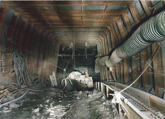
Bottom of Gascoigne Wood Drifts showing the start of the spine tunnel developments
The tunnels were then driven in the Lidgett Seam which is approximately 65 metres below the Barnsley seam at a gradient of 1 in 33 heading east. This level gave the correct depth for the future staple shaft bunker installations at the individual pits. The roadheader progressed well up to the 1600m mark using 17 x 12 ft arch support girders. This was the point where the Robbins TBM erection chamber was constructed in the South Spine Tunnel. The North Spine Tunnel Dosco Mk3 Roadheader progressed at around 65m per week to achieve the first connection with Wistow Mine.

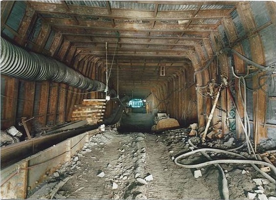
Gascoigne Wood spine tunnels showing connection to Wistow Mine
The Robbins 193-214 Tunnel Boring Machine erection chamber was created in three separate part using benching of the strata due to the sheer size of the 240 tonne machine. After the initial cuts were completed and square section girders with shutterings were installed the top section of the chamber was concreted with heavy duty lifting beams installed to handle the weight of the machine sections. The middle 2.5m section was cut and concreted. The lower 2m was cut with a semi circular base to allow for the 5.8m circular cutting head to be installed. When completed the chamber was over 40m in length, 6.8 metres wide and 8.6 metres high.

The Robbins T.B.M.Erection Chamber
The Selby Coalfield was designed and developed using the very latest mining technologies and equipment. Gascoigne Wood mine development was no exception. Flameproof laser beams were used in the underground tunnels by surveying teams for complete accuracy from the start of the mine. The lasers were very heavy pieces of equipment and were mounted in the left of centre in the roadways. The large mounting brackets were manufactured from girders and needed four, two metre roof bolts to anchor the equipment in the roadway. During the early use of the lasers it was realised that in dusty conditions the integrity of the beam was diminished. The beams were refocused by the manufacturer to give a sharper, intense beam for surveying to take place. The lasers had to be moved forward every 150 metres, which was often less than a week due to the rapid development speeds in the Robbins TBM South Spine Tunnel.
The surveying team at Gascoigne Wood used various systems to cross reference and ensure the accuracy of the spine tunnels. All the Selby mines were referenced to the Ordnance Survey Grid Reference System which is known as the British National Grid (B.N.G.).

Gascoigne Wood Mine
Gascoigne Wood Mine had a marker point beacon on the covered stockyard (marked Coal preparation plant on photo) with other points in the area being on the top of the winders at each of the five satellite mines marked with flashing beacons for reference. Carlton Towers, Pontefract Water Tower, Sherburn Church and York Minster were also reference points in the area. Andy ‘fondly’ remembered carrying huge batteries up to the top of the 72m high main tower at York Minster, through the very tight internal staircase, to power the beacon.

York Minster Towers
He then set up a tripod with a theodolite and measured to the flashing beacons on the winder towers at the satellite mines and the covered stockyard at Gascoigne Wood. This process was repeated at each pit to achieve the triangulation surveying readings.

North Selby Mine Winder Towers
These surface reference points along with the huge amount of borehole depth, shaft depth data and use of the laser beams ensured the accuracy of the spine tunnel developments.
As the spine tunnels progressed connections were made to Wistow Mine for ventilation and the coal clearance system which was operating from January 1983. Ventilation slits were also made between the spine tunnels to improve the working conditions in the headings. The plan was to connect to Wistow, Stillingfleet and Riccall mines for ventilation and coal clearance.

Spine tunnels between Wistow connection and Stillingfleet Bunker 5 and 6
As the spine tunnels progressed past the second ventilation shaft from Wistow at 7916m mark the next planned ventilation connection was Stillingfleet Bunker 5 and 6 at a gradient of 1 in 12.9 towards the east. During this stage of development in the South Spine Tunnel the extreme temperatures were getting increasingly difficult due to distances from ventilation boreholes. The heading teams were increasingly suffering with heat stroke with men collapsing on multiple occasions and had to carry up to 10 litres of water to get them through the shift. At the back of the pantechnicon a water storage tank for the TBM cutting water was sited. Andy used this on occasions to cool his arms when having the signs of heatstroke as it was slightly cooler than the ambient temperature of over 45° centigrade. Incredibly the teams operating the Robbins machine achieved tunnelling rates in this period which culminated in a world record breaking week in January 1986. 19m in one shift, 43m in one day and 152.3m in a week.

The world record breaking AMCO Heading Team January 1986.
Due to the high cutting speeds of the Robbins TBM machine, the North Spine Tunnel Titan E134c Roadheader was unable to maintain the same rates and started to lag. Due to the unavailability of ventilation slits and problems with the ventilation connection road from Stillingfleet Mine at Bunker 5 and 6 the South Spine Tunnel heading was nearing the limits of the available air flow from a single leg ventilation.
In early 1987 the Robbins TBM machine hit an area of very soft ground. The development stopped for a few weeks for remedial work. At this point a tunnel was started from Riccall Mine called the Stillingfleet Connection running above and parallel with the projected South Spine Tunnel. When this roadway was completed a 1 in 1 drift was driven down to the South Spine Tunnel using 10 ft x 8 ft arch girders to give a ventilation connection with Riccall Mine. The Robbins TBM went onto complete the South Spine Tunnel on the 22nd June 1987. Andy supervised the surveying work and completion of the Riccall Mine No 7 and No 8, 7.5m diameter 60m deep staple bunkers and bunker slits. The Robbins 193-214 Tunnel Boring Machine continued driving forward at the completion of the development and was abandoned.

The completed spine tunnels at the Riccall bunker connection.
Andy went on to work at Riccall Mine for six months and then gained promotion to Kellingley Colliery in 1989 as Deputy Surveyor and then Unit Surveyor where he stayed until the closure of the pit in Dec 2015.
Many thanks to Andy Mortimer for his time and information provided for this post.