Plan above showing Riccall Mine south side faces showing faulted area on H443s coal face panel.
During the development of H443s face in August 1988 a section of sandstone intrusions appeared in the heading at 730m mark. These intrusions continued for over 100m and then disappeared. The decision was made to continue with the headings to full distance and start the face as planned at 1600m mark. As the face retreated a plan was created to transfer the equipment onto a new face line which bypassed the faulted area and continue with the face. The loss of production was a problem but another issue was on the horizon which was the royal visit by Queen Elizabeth and Prince Phillip planned for the 9th December 1989. Below is the step by step planning document created by the management team overseen by Denis Allchurch, Riccall Mine Deputy Manager and all the departments responsible at the mine for the timely and safe transfer of equipment from one face to another.
Covering description from Denis Allchurch
Acknowledgementsof staff
Critical path analysis
Bolting and meshing
Building new shearer and dismantling existing shearer
Maingate move out
A.F.C. salvage, cables and hoses
Powered supports
Electrical co-ordination
As you can see from the booklet above describing the face to face transfer, the process of moving thousands of tonnes of equipment in such a short time is incredibly difficult. Organisation and briefing with experience and input from all the staff is the key to safe working. As you can see from the mine plan at the top of the post the face ceased shearing coal on 11th October 1989 and the new face was shearing coal on 7th November 1989. The transfer left a month for the face to be established before the Royal Visit.
Many thanks to Denis Allchurch, Riccall Mine Deputy and later Mine Manager for the information in this post.
Stanley Main Drifts showing Pit Bottom area, West and East developments of the mine.
Stanley Main Drifts when completed.
During late 1997 a series of canteen meetings with the staff were called at Riccall Mine. An announcement was made that Whitemoor Mine and Riccall Mine were to become a combined mine and that Whitemoor was to be closed in 1998 when the last face was worked out. We were also told by the manager that Riccall Mine would produce coal for seven more years if we were lucky. Riccall men were told that they had options to either stay at Riccall Mine until closure, apply for redundancy, transfer to Wistow Mine or go to Whitemoor Mine to work the last face, which was H635s and then be redundant. These options gave the chance for any Whitemoor men to transfer to Riccall.
Rumours were rife from 1992 that the Selby Coalfield was under threat of closure due to diminishing coal contracts with the two newly privatised energy generators but to be actually told was a surprise as we had achieved exceptional production figures for many years. The announcement was also made that Riccall Mine was to develop drifts up into the 2.5 m thick Stanley Main seam for the last few years of production which was another big suprise as the Selby Coalfield had planning permission for the Barnsley Seam only.
The application for planning permission to work the seam was presented to North Yorkshire County Council in mid 1998 and was passed in July 1998 without major objections. The permission was to mine 9 million tonnes of Stanley Main Coal. Permission was also granted in 1999 to tip the waste from the Stanley Main Drift developments at the Gascoigne Wood tipping site.
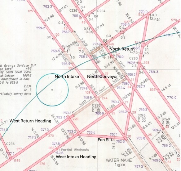
The Stanley Main Drifts junctions were 250m from the pit bottoms in the North Intake and North Return roadways. Skanska were chosen as the contractors for the work to be carried out. The first drift to start was the Intake which started development in early 1999. The junction was created with a Boart Multi Drill Rig using boring and firing. The drift progressed on an upward North East incline at 1 in 16.
When the Intake Drift had reached 70m a junction was created. The Boart Drill rig then turned to the East and drove an 80m heading at 1 in 23 on an uphill incline. The junction for the Return Drift was created in August 1999 and the Boart Drill rig then drove back South West at 1 in 20 downhill to create the circuit to the North Return which was completed in early 2000
The Intake Drift was developed with a Paurat Titan E134b Roadheader using heavy duty arch supports.
The development of the Intake Drift from the cross slit started in May 1999 and drove at an incline of 1 in 12 uphill. It passed through the Dull Seam, Kent Thick seams and the Kents Thin Seam reaching the Stanley Main Seam in late Dec 1999.
The Return Drift was started in September 1999 and was driven by a smaller Paurat Titan E169. The heading progressed well at 1 in 20 on an uphill incline and reached the Stanley Main Seam in April 2000. When the junctions for the Stanley Main Intake and Return Lateral headings were made a roadway was driven west from the Intake lateral junction back towards the North Conveyor Road. A borehole was made for the Stanley Main coal to load onto the North Steel Cord Conveyor from the Stanley Main level.
The Paurat Titan E134b and E169b Roadheaders were made under licence by Dowty. Below are a couple of information sheets for the machines very similar to the machines used in the Stanley Main Drift headings.
Information for the post was provided by Phil Wright, Ian Steele, ( Steely ) who worked for Skanska in the Stanley Main Drifts and Kevin Grant, S.C.E. at Riccall Mine.
When production had started at Riccall in Jan 1988, the conditions at the bottom of the Bunker 7 and Bunker 8, which was the furthest point in the spine tunnels at Gascoigne Wood were extremely hot and dusty. Booster fans were urgently needed to cool the area and improve ventilation. A 1 in 7 drift was driven from the North Intake at Riccall Mine into the Gascoigne Wood Wood south spine tunnel to remedy the ventilation problems.
Riccall Mine / Gascoigne Wood, 1 in 7 Booster Fans.
AMCO were given the contract to drive the heading with a Dosco Mk2A revised hydraulics roadheader. The heading started in April 1988 and finished in March 1989. The heading drove on a 30° dogleg for 30m then turned north east to drive at an incline of 1 in 7 under the Riccall Bunker area and completed at the junction where the south spine Robbins TBM was laid to rest.
The heading was driven from a junction 500m outbye from the North Intake junction with Bunker 7. A conveyor was installed from the 1 in 7 junction to the bunker 7 conveyor coming from the Riccall bunker. A drift conveyor was installed loading onto a short conveyor to the North Intake junction. This conveyor loaded on to the floor where it was pushed outbye into the North Intake slusher bunker. The heading muck was loaded at a later time, using the slusher, onto the conveyor. This allowed for sufficient cutting muck storage.
As the 1 in 7 heading progressed it cut through the Dunsil and Swallow Wood seams as it passed throught the cross measures. Two Pikrose haulages were installed in the short heading and the 1 in 7 drift heading, at the top junction, to supply the development and transport the substation installation equipment. Two hundred metres from the Gascoigne Wood junction the heading was widened and two parallel headings were created either side of the main heading for the booster fans installation. The heading continued forward and completed to Gascoigne Wood in early 1989.
At the booster fan switchgear site, concrete tiered pads were created for the 6.6kv substation, including 3x 6.6kv MIVAC switches, a 6.6kv HF2VG double drive control panel for the two 750kw booster fans, local 6.6kv/1100v transformer to supply the Elram control panels, MINOS outstation and lighting transformers. Double electrical Elram operated ventilation doors were installed in the main roadway outbye of the substation.
The 6.6kv supply for the substation was a dedicated supply from the surface via No1 shaft to a MIVAC shunt trip switch in the No1 pit bottom main substation. 250m lengths of 120mm 6.6kv armoured cables were run from the substation along the North Intake roadway and were connected using Scotchcast inline joints. It was quite a job jointing and hanging the cables in the middle of winter in the main intake.
When the 6.6kv supply was energised the commisioning of the fans took place. Booster fans are an integral part of a mine ventilation system so many air pressure, air velocity, methane level, leakage and flow checks were made as part of the environmental systems at both Riccall Mine and Gascoigne Wood to ensure no problems were caused with the new installation.
The control, monitoring and system transducers on the fans were checked including fan vibration, bearing vibration, bearing temperature, air pressure, air flow and automation system for stopping and starting the fans from the surface control room at Riccall. When all the checks were made the fans became operational.
Water pumping systems were also installed at the spine tunnel tail end which used the 1 in 7 Drift to clear mine water via Riccall Mine.
The South West Trunk road was driven by Thyssens using a Dosco Mk3 roadheader. The roadway was driven from the West Conveyor at H472s cross slit to the south of the mine to connect with Whitemoor Mine. It was driven in two sections. The heading started in Aug 1989.
The South West Trunk.
The first part of the South West trunk headed south and created junctions for H478s maingate and H479s face. H480s junctions were started at slightly later date. They then continued onwards to create a major junction for the South West Lateral, known as Angina Hill. The heading then continued towards the demarcation with Whitemoor Mine to join with the Whitemoor West Conveyor roadway to create an intake roadway. When the heading got to the South West Lateral junction the coal, due to a downthrow fault, dipped so a small shallow drift was made. The heading then continued to the Whitemoor connection creating 2 further face junctions for H437s on the westside and H439s face on the eastside of the heading. The original plan for this area of the mine was to continue 1000m with the South West Trunk heading a and create a further junction. At this point a lateral roadway was to be driven to develop faces at the West and East. This development never happened.
Dosco Mk3 Roadheader
The furthest face to be worked from the West Return of the mine was H477s. This face was on the boundary with Wistow Mine. The face finished in September 1995 and was made ready to be transferred to the first face on the South West Trunk which was H478s. This face was planned to start in early 1996. This face used the West Conveyor Road as the tailgate for the face so only the maingate had to be driven.
The H477s pantech of electrical equipment and transformers were sent out of the mine for overhaul leaving only a pump and tank for the transfer. The stageloader, face supports and AFC were tranferred from the maingate through the cross slit between the Return and Conveyor road straight onto the new face. A refurbished electrical pantechnicon including pumps and tanks was installed from the surface via the new H478s maingate. As the face retreated it had to passed through every junction from H477s to H472s which was quite a task due to the height of the return roadway.
The face had retreated 200m when an urgent modification was needed to both of the transformer Wallacetown B80 LT end supplies. They needed replacing urgently due to a technical problem with some internal contacts. We spent two very long weekend shifts getting the new switchgear onto site, removing the faulty switches, fitting new items and getting the defective unit out of the pit. The face progressed well and was completed in September 1996.
The face equipment from H478s was transferred to H471s.
The next face to be developed from the South West Trunk Road was H437s. This face was developed at the inbye end of the trunk road near to the junction with the South West Lateral.
This face was installed in late 1996 using Longwall International equipment with an Anderson Strathclyde AM500 DERDS. The next expected face developments to the south were never started and when H437s face had retreated a short distance a seismic survey was carried out from the main gate testing the seam to the south of the mine. This survey apparently showed that the coal had faulting and due to the low risk mining strategy undertaken by RJB Mining, a huge area of coal was abandoned to the south of Riccall Mine. H437s proved to be a good face with no geological issues. Wistow Mine subsequently worked 3 longwall faces, H93s, H94s and H95s adjacent to H437s. The area of the coal abandoned was equivalent to the coal worked at Riccall Mine during it’s production life.
The next face to be worked from the South West Trunk was H479s. The 1500m face developments were started in January 1998 using Lee Norse LN 800 Continuous miners. The 150m face line was situated on the Wistow Mine boundary at the side of H46s and was worked from West to East. The face was equipped with a Joy 4LS shearer and face equipment. The electrical equipment and pumps were ex H437s. The face started production on 10th August 1999 and completed production in 6 months on 28th February 2000.
The last face to be worked from the South West Trunk was H480s. This face started development in November 1999 and started production on 24th August 2000. The face headings were 1250m long with a face length of 230m. This face was installed with Joy equipment, Joy 4LS Shearer and a 3.3kv Baldwin and Francis CHL Load centre (ex Kellingley Colliery) to control the electrical equipment. The face produced extremely well and was completed in 8 months.
Plan showing all the faces worked at the West and South West of Riccall Mine
Plan showing the South West development from the South Intake roadway.
The South West Conveyor lateral roadway was started in November 1991 by mining contractor AMCO using a Dosco LH1300 roadheader.
When the Dosco LH1300 arrived at Riccall Mine it was painted a strange pale blue colour. I later became aware that machines in this colour were owned by the contractors AMCO.
Dosco LH1300 Roadheader.
The heading was driven on an uphill incline from the South Intake junction heading towards the junction with the South West Trunk being driven by Thyssens and was nicknamed Angina Hill. At the same time a cross slit and conveyor was developed from the South Intake towards the South Conveyor to transport coal from the faces planned in the South West area. When the connection was made with the South West Trunk this roadway became the supply road for the trunk roadway. A manriding conveyor was installed when the connection was made.
The first face to be developed was H430s which was driven 800m using LN800 continuous miners and started production in September 1992. The face equipment and A.F.C. were Dowty Meco equipment similar to H444s but with a new rail mounted pantechnicon, electrical equipment, transformers and pumps. The shearer was an Anderson Strathclyde AM500 DERDS. The face retreated from north to south and progressed well completing production in May 1993. The face equipment was salvaged and transferred to H432s face.
The South West faces ( H437s, H438s and H439s not shown)
As the South West heading progressed, junctions were made for four faces, H430s to H433s, to be worked to the north. A roadway was later developed in 1995, heading South from the lateral to develop H438s and H439s faces.
H432s, which had gates of 1200m, started production on 26 July 1993 and completed in Jan 1994 for the equipment to be transferred to H433s face which was 1000m. This face started production in March 1994 and completed in late September 1994. The equipment was transferred to 1000m, H431s, which started production in November 1994. All the faces in this block of coal were developed using Lee Norse LN800 continuous miners and created european drivage records during these developments.
Lee Norse LN800 continuous miner.
The faces were successful and helped Riccall to achieve record production figures during this period. All the faces were equipped with Dowty face equipment and Anderson Strathclyde AM 500 DERDS shearers with identical rail mounted electrical systems and were all supplied using Clayton BoBo locomotives. The last face on the north side of the South West, H431s, completed production in mid 1995. The next face H438s, was taken from the south side of the South West roadway. A slit was driven going south and a short face was developed with the headings driving West towards the South West Trunk. This face was installed using H431s equipment and started production in Sept 1995 and finished in Mar 1996
The slit gate from the South West roadway continued for 300m and a further face H439 was developed. The face development roadways went all the way to the South West Trunk. The face was installed in the slit gate from the South West roadway. This face used the equipment from H438s.
H439s had a huge slip fault, what we knew as a white wall, 70m from the main gate. This caused huge problems with the shearer and chocks due to the steep angle of the fault. The problems with bad ground around the fault stopped production for periods of time to enable grouting in the faulted area. Eventually the face conditions became too unsafe and the face was abandoned at the half way mark. Attempts were made to salvage the face supports but due to coal being left in the waste area at the back of the face from the faulted area an heating developed, known as a gob fire and the face had to be sealed off. Explosion proof seals were immediately instigated at the face gate ends off the South West Trunk roadway. When they were completed, nitrogen was pumped from the surface, via an existing pipe range, by a rig supplied by NOWSCO to control the heating but the face and all the equipment was lost.
In early 1990 the third phase of the development of Riccall Mine started. A roadway was driven from the first junction 500m from the pit bottom in the North Return. The roadway was driven at 45° to the junction and was the start of the east side of the mine. The cross slit was completed in Sept 1990 with three headings planned to be taken from this roadway, the East Conveyor, East Return and 2nd Return to the pit bottom. This roadway was the East Booster Fan Return.
Plan of East Development cross slit.
The start of the East Conveyor roadway was from the North Return driving East and was started in January 1990. The heading was completed to the east developments cross slit in May 1990 and the conveyor was installed for the lateral headings. The conveyor loaded onto a newly installed conveyor in the North Return which loaded into the Riccall bunker area.
Thyssens were given the contract to drive the east developments. The East Conveyor and East Return were driven at a 1 in 17 downhill incline using Dosco LH1300 roadheaders and were started in Oct 1990.
Dosco LH1300 Roadheader.
As the east lateral headings were developed, junctions were created at H500s and H501s. The cross slit was created for H501s main gate and the face headings for H501s face were started from the East Return. The face retreated from South to North. The Lee Norse LN800 machines were tracked on power from the west of the mine to be used for the H501s face headings.
Lee Norse LN800 Continuous Miner.
The East Side from H501 to H505s.
East Side from H499s to H503s.
In April 1991 when the heading team were starting the face roadway for H501s, the 2nd East Return was started. This Thyssen’s heading was driven using a Dosco LH1300 and headed south, back towards the No2 upcast shaft, parallel with the North Return. At the No2 shaft end a new inset was constructed 20m below the manriding level, which was completed in Dec 1991. A booster fan was installed to improve the air flow to the east headings and faces. It was completed before H501s face commenced production.
A little side note to this fan installation; After a couple of years of running, the fan started to show a slight increase in vibration on the MINOS monitoring system. The vibration increased over a few days and a few people were getting very concerned. Gary Crossland, my mate who was a whizz on the Vibration Spectrum Analyser, loaded the fans installation data into the machine and did some tests on the fan. He found the vibration to be one particular fan impeller with dusty debris build up. A planned stoppage was organised and the problem was sorted.
2nd East Return showing booster fan.
The H501s tailgate heading was started in Mar 1991 and completed in Sept 1991. The machine turned east to cut the faceline which was completed in Nov 1991. The LN 800 then turned north to start the main gate heading back to meet with the main gate LN800 which started cutting in Nov 1991. The headings connected in Feb 1992 and both machines were driven off the main gate together to start the H502s face developments which commenced in March 1992. The face commenced production in May 1992. The face was 240m long and the gates were 1300m in length at a depth of 825m.
The face equipment on H501s was ex south side Dowty face supports and A.F.C. which had been overhauled and redesigned to be compatible with the new 390kw Joy 4LS shearer. The electrical equipment, pumps and two, 1 MVA transformers were rail mounted with a Wallacetown M82 face isolator situated outbye and 100m of type 6.6kv type 631 pliable wire armoured cable to allow for the face retreating. At the inbye end of the main gate, an Hausherr dinting machine operated where the stageloader loaded onto the conveyor. 30m of flexible, double back to back Bretby was used to protect all the face cables and hoses where they went from the pantechnicon into the stageloader cable protection troughs and to allow for the face retreating. The 150kw stageloader had a 150 kw crusher/ sizer and the face panzer had two, 150 / 300 kw 2 speed motors.
Due to the 825m depth of the workings, roadway conditions were slightly concerning with floor blow becoming apparent. The maingate was started with a remedial system of cable bolting carried out by a new team set up at the pit. 28 foot cables with concrete grout were used for these secondary supports. The bolts were crossed and tensioned to create what looked like an heavy duty basket weave across the roadway. This system of support became the standard practice on all developments at the east of the mine.
H501s performed very well. Floor blow in the tailgate was a concern so extra concrete support chocks with steel wire reinforcing called Fibcrete Blocks were installed near to the tailgate face entry but extreme floor heave still caused problems causing very confined working, especially for the methane borers at the back of the face.
H501s finished production in Jan 1993 and H502s started production in Feb 1993.
H502s “Askern Pirates” team with Reg Goudie on left, Deputy Shaun Hager, Chick Sharrett, Alan Longfield, Mick McVeigh and Phil Scorah
Due to the problems with extreme floor blow on H501s the cable bolting support system was introduced whilst the headings were being developed on H502s. Before the face started production a three man dinting team was set up to pre dint the main gate outbye of the pantechnicon. The dinting team lifted the rails and conveyor in sections and cut 1m of floor muck. The equipment was then restored. The three man team used a Dosco Dintheader with a MC3 Scorpion tail loader.
Dosco Dintheader
Mavor and Coulson MC3 Scorpion.
The dintheader cut the floor which loaded onto a monorail mounted bridge belt and onto the front of the MC3 loader. The muck was then loaded via the swivelling scorpion tail onto the maingate conveyor. The MC3 was designed in the 1950s and was a machine from a bygone era but proved to be a very versatile machine.
As the East lateral roadways progressed a further machine was introduced by Thyssens. The Voest Alpine AM75 was a low profile machine and weighed 58 tonnes. It had a transverse cutting head arrangement with a 200kw cutter and a total power of 350kw. The machine performed very well. The other machines used were a Dosco LH1300 in the lateral roadway and a Lee Norse LN800 continuous miner to develop the face roadways. As the East side of the mine developed the temperatures became extremely hot due to the depths and distances. The headings were over 40c and heat exhaustion became a problem.
The face development roadways at the East of the mine were gradually getting longer. The coal clearance conveyors were getting too long for a single conveyor drive to handle the production from the face so booster belt drives were installed on maingate coal clearance conveyors. The booster conveyors were installed 150m inbye of the main double 150kw drive gearheads . The booster belt was the same rating of 300kw but ran inside the existing conveyor. Due to the weight of the coal on the top conveyor the belt pushed down onto the lower booster conveyor which assisted with the load due to friction between the conveyors. Booster conveyors were used on all the east side coal faces from H503s to H506s due to the coal face production conveyors being in excess of 2000m.
The first time I heard about this type of conveyor drive was when my dad was part of the mechanical team who installed a booster drive on the Royston Drift Mine, main drift conveyor.
At the end of 1993 the installation of a new Steel Cord Conveyor was started. The conveyor was a double, 6.6kv, 750kw drive with an option to add a third 750 kw drive. The drives had scoop starters with huge, double disc braking anti roll back system. If all 3 drives had been used it would have been the most powerful conveyor drive ever installed underground in a coal mine at the time of installation. Only 2 X 750 kw drives were ever used. The substation, 6.6kv NEI Peebles HF2VG switchgear and control equipment were sited between the end of the East Return and the North Return roadway on a large suspended Purdy platform set back to allow the huge drivehead sections and 16 tonne rolls of steel cord conveyor to pass through. A large clamping and vulcanising station ( cooking facilities) was built at the end of the drivehead for the conveyor belt jointing.
East Conveyor Manrider looking inbye
The conveyor delivered onto the Riccall Steel Cord Conveyor via a short 1 in 3.4 Drift at the outbye end of the East Conveyor. This short Drift was completed in April 1994.
The conveyor was installed when H502s finished production. The return end was inbye of H504s maingate and became a manrider when the installation was completed.
When the H503s gate developments were completed a face line was driven from the maingate to the tailgate. As the faceline was being cut, the conditions in the heading became very problematic with floor blow and heavy weighting happening as the roadway was developing. It became apparent that the roadway was becoming unusable as a faceline. The heading was completed and the Lee Norse LN 800 machine was tracked out of the tailgate 100m and a junction was created for the new faceline. This was cut from the tailgate to the maingate. The original faceline was used as a sacrificial heading to take the weight off the new development and was allowed to close up. This caused a problem for production due to the delay in developing a new faceline heading so a decision was made to build the entire pantechnicon in the maingate between the new faceline junction and the sacrificial heading. This allowed the faceline to be completed and the removal of the heading machines by tracking out to the new H504s face developments. The face A.F.C. gearhead, stageloader and crusher, pumps and electrical equipment were installed in the disused inbye roadway. The equipment was then pulled into position when the faceline was completed and the heading machine were removed from the maingate roadway. This was the hottest place I have ever worked in a mine with temperatures of 50c due to roadway air flow in the severely restricted faceline roadway.
During the conveyor installation, the face installation on H503s face was completed using the equipment from H502s. During this period there were no manriding conveyors so a lot of long walks were involved with some very long shifts in extreme heat as the face gates were 2000m in length and an overall walk of well over 4000m from the pit bottom to the face and back at the shift end up the 1 in 17 East Conveyor Road.
H503s proved to be a very good production unit due to good face conditions and main gate roadway dinting taking place to relieve extreme floor heave. The face completed production in December 1994.
The next face to be worked at the East of the mine was H504s. To say that this face was a disaster is an understatement. The face headings were developed using LN800 Continuous miners with supplementary cable bolts as supports. H503s face equipment was transferred and installed. Production started in early 1995. The face started ok but within 200m of retreat the face conditions became very heavy with severe cavities and faulting. Many remedial systems of face repairs were tried including different types of concrete pumping, grouting and cable bolting.
H504s face showing faulting.
A pumped, two part resin glue brought from Germany was tried with some success. Unlike standard roof bolting, using resin capsules, this polyurethane two part resin is injected through the hollow bolts called IRMA’s, under pressure, after the bolt is inserted. The polyester fills the surrounding strata around the bolt including any cracks in the surrounding rock and ensures complete encapsulation when working in bad ground.
(Above information kindly provided by Denis Allchurch, Deputy and Mine Manager at Riccall Mine)
The face conditions were so bad that production ceased for weeks on end. As the face was being cut it was collapsing with the chocks eventually unable to move due to severe weighting. The A.F.C. became unusable due to the amount of stone and weeks were spent clearing the panzer. As the face retreated the cycle of roof collapses continued and equipment became unusable. The decision to abandon production on H504s was made and the face finished on 17th April 1997, 200m short of the planned finish mark.
The next face was H505s face which was developed and installed during the production run of H504s. The face gates were over 2000m long. A brand new set of Joy face equipment including 4,500 psi face support pump system and electrical equipment along with three 1.5Mva transformers were installed on this face . It was the first time an LC33 electrical Load Centre was used at Riccall Mine. The Joy 4LS shearer, A.F.C. and crusher/ stageloader were all 3.3kv.
The panzer and crusher / stageloader were fully automated using a Davis outstation to control the face coal clearance which was another first at Riccall Mine. Production started in 1996 and completed in 1997. The face was a total success, with very good production figures, very unlike the H504s nightmare face.
During early 1996 a junction was created in the East Conveyor roadway opposite H505s Main Gate. This heading was called the North East Development. The heading was driven to the north of the mine by Thyssens contractors using a Dosco LH 1300 Roadheader. When the heading had progressed 200m it turned 45° and started driving on a North Easterly direction. A 6.6kv ring main supply and electrical substation was created for the North East faces at this junction. The lateral roadways were to develop up to twelve longwall faces starting with H514s but were never developed as the mining contractors were withdrawn. This area was abandoned in August 1996.
North East Development Thyssens heading team, Mick Holland (Tunnel Tiger), The Johnsons, ( Polly, Andy and Jonny) Joe Perlich and Malc Turner with Dosco LH1300.
Thyssens North East conveyor installation team, Graham Silcock, Ian Cracknell and Mel Fletcher.
The next face to be worked at the east of the mine was H500s. This face was a shorter face at 150m and was installed in early 1998. The face was totally automated using LC1100 and LC33 load centres with a Davis Outstation controlling the face coal clearance and face support hydraulic pumps. It was a very high tech face and produced very well. The face was completed in four months starting production in June and finishing in October 1998.
From production starting in January 1988, Riccall Mine was a great producer of coal. It had it periods where individual faces were problematic but due to working multiple faces the production remained high throughout it’s working life. It was the first mine in the complex to produce more than 2 million tonnes in less than a year on 14th March 1992 finishing the year producing 2,200,000 tonnes.The following year year production was up again to 2,579,000 tonnes and in the year of privatisation, Riccall produced 3,060,000 tonnes, the first pit in Europe ever to produce over 3,000,000 tonnes of coal in a year.
In its short life of 16 years Riccall worked 43 longwall coalfaces with exceptional production figures over the life of the pit. It was also the only mine in the Selby Coalfield to work two seams, the Barnsley and Stanley Main seams. The Stanley Main seam faces were designated SM and were worked over the east side coal faces.
The North Conveyor Mk2B Roadheader at 194mmarkin 1985.
When the North Conveyor heading had progressed 700m in Feb 1985 a large junction was created. The Mk2B roadheader then continued on to the north of the mine. At the same 700m point in the North Intake heading in Feb 1986, a junction was created and the cross slit was created between the North Conveyor and North Intake roadways. At the North Intake junction, an heading was started, to develop the coal at the west of the mine. When the heading had progressed 100m a further junction was created. The machine turned right to create a 70 metre cross slit for the West Return and West Intake stub headings. The machine then drove an heading back towards the North Intake at 45° to create a ventilation slit for the heading fans and loco access. This development was phase two of Riccall Mine, to access the coal at the west of the mine up to the boundary with Wistow Mine.
In October 1986, the North Return and North Conveyor lateral roadways were completed. The South Conveyor was completed and the Return was well advanced. Both North and South Intakes were half completed and face developments were also started on both sides of the mine. This was the first phase of the development of the mine.
The West Development Headings.
In Nov 1988 the west development headings were started by mining contractors, Thyssens. The machines used for the West Conveyor heading was a Dosco Mk2B roadheader and West Return headings was a Dosco MK2A revised hydraulics roadheader. The headings were supplied by two Becorit battery locos owned by Thyssens. These locos moved equipment from a transhipment point at the bottom of the West Conveyor roadway.
Before the West Return lateral heading started, the West Return connection roadway, to the North Return, had to be completed. It was a 1 in 17 drift changing to a 1 in 5, driving above the North Intake and North Conveyor roadways. The connection, a 1 in 1 Drift, was created upwards from the North Return, using bore and fire with a slusher to muck out, to complete the heading. This drift was called Zolly’s Drift after the Thyssens general foreman. This allowed the West Return air to travel to the upcast No2 shaft.
The West lateral headings progressed and made junctions for H471s and H472s faces. The West faces were to be taken off the West Return retreating in a north to south direction. The first face to be developed was H472s. These headings were driven by Thyssens using Lee Norse LN800 2.5tt continuous miners and were supported using arch girders.
H472 Face and South West Trunk.
H472s face development gates were started in March 1990 and the 700m face headings, including 230m faceline, were completed in Oct 1990.
The cross slit between the West Return and Conveyor Road was completed and the west side 6.6kv ring main MIVAC substation was built in the slit, at a later date, to supply all the 8 west faces and and headings. A roadway was taken off the West Conveyor called the South West Trunk.
H472s coal face was the first one at Riccall Mine to have a Joy shearer. The first Joy shearer used in the country was at Manton Colliery on 39s face. It was a 3LS and proved very successful. At the time H472 was to be installed, 2 shearers were made available for Riccall Mine. A Joy 4LS and the ex Manton Colliery, Joy 3LS. It was decided that Riccall Mine had the Joy 3LS and Trentham Colliery got a new Joy 4LS. The 485kw, 3LS installed at Manton Colliery and then Riccall Mine, was the only one ever used in the U.K. and is now on display at the National Coal Mining Museum.
Joy 3LS Shearer cutters
The Joy 3LS was a brilliant coal cutter. It was a very powerful multi motor shearer capable of unbelievable cutting speeds. The combined horsepower of the machine was over 600 horsepower with each of the two cutter motors rated at 250 horsepower. The hydraulic onboard pump, and the D.C. traction haulage motors were a combined rating of 100 horsepower. The hydraulic pump was used purely for moving the ranger arm rams.
Shearer D.C. drive unit.
The 2×35 Horsepower D.C. traction motors were thyristor controlled with speed control set using a programmable electronic module. The traction drives operated a gear which sat on a huge captivated chain to haul the shearer through the face. We were told that when used in the American mines, where the face workers didn’t work on the tailgate (dusty) side of the shearer, the machine could cut at 60 feet per minute. We had stricter dust regulations in the UK so these speeds were restricted. The shearer driver operated the machine using a remote control powered from his lamp battery via a lead.
Shearer control panels.
The machine had a control section with an LED diagnostic panel situated in the middle section which was useful for fault finding. The cutter drums on the shearer was so designed that if it struck a solid object such as a chock beam, the output shaft from the ranger arm, to the cutter, sheared to ensure no damage to the gears of the ranger arm occurred. It was called a quill shaft.
H472s face was developed, as mentioned earlier, using Lee Norse continuous miners using arch supports. It was ready to start production in Jan 1991. The main gate pantechnicon was rail mounted and the face equipment was Gullick Dobson transferred from the northside of the mine. The face was very successful, finishing production in June 1991.
H472s face team with methane borers.
All faces at Riccall Mine had the entire electrical equipment, including transformers, returned to the surface, on every face, for a complete overhaul, redesign and testing. As the electrical equipment evolved, due to electrical developments, plug and socket connections were fitted, where allowed, for ease of salvage and installation.
West side faces from H470s
West side faces from H472s showing South West Trunk development.
West side faces from H474s H477S.
Lee Norse LN 800 continuous miners were used for all the West Side face headings with high rates of developments achieved due to the seam section becoming thicker as the mine progressed westward and the introduction of total bolting as the primary support system. The last 3 faces at the west of the mine were supplied with face equipment from the newly formed mining company, Longwall International, a merger of Meco International and Dobson in Jan 1993.
As the West lateral developments progressed the conveyor system was changed due to the length of the drivages and the faces worked. The slit from the outbye end of the conveyor road to the steel cord had a Huwood double drive which delivered onto the steel cord conveyor. A further Huwood double drive was installed just inbye of H472s slit supplied by an Wallacetown H65 installed on a large purdy platform outbye of H472s.The platform had to be built with sufficient height to allow men to walk underneath so we built the switchgear on the platform and then lifted the entire platform as high as possible. The conveyor became a manrider except for a short section at H472s junction where the South West Trunk delivered on the West Conveyor.
West Conveyor Manrider
West Conveyor Outbye
H477s Maingate end
The face taken from the inbye end of the West Return was H477s with a seam section over 3m and the chocks working on there limit. The equipment was then transferred to H478s which was a face developed on the West Side of the South West Trunk roadway. The next two faces taken off the West Return were H471s with 1000m gates and H470s with 550m gates. These faces used the equipment from H478s and were very successful faces both completed by Feb 1998.
Photo above shows the H471s face team in mid 1997. The lads shown are top row, left to right; Steve Priestley (Tiger), Andy Lister and Bob Yorke. Middle row, right to left; Ian Liptrot, Eddie Jordan and Steve Commons (Old hand). Front row, left to right; Roy Minett, Paul Morton (Pinky), Willie Baxter and Paul Ward. The photo has been kindly given to me by Ian Liptrot who has a copy from the RJB News magazine. It is taken at the main gate entry to the face.
The last two faces worked on the west side of Riccall Mine were developed from the West Conveyor roadway. These were very short faces to remove the final couple of blocks of coal at the west side of the mine. H434A’s development was started in September 1997. The Main Gate was driven with a Dosco MD1100, a 34 Tonne, 157 kw, medium sized roadheading machine.
Dosco MD1100 Roadheader.
West side H434A’s and H434B’s face plans.
H434A’s tail gate was driven along with the face line heading and then abandoned on 20 Feb 1998. In June 1999 the heading was de-gassed and development was restarted to complete the main gate roadway back towards the West Conveyor roadway. The heading was completed in September 1999. The face, which had 400m gates and a face length of 180m was installed and started production in January 2000 using a Joy 3LS Shearer with Joy face equipment and standard Wallacetown SIMOS 1100v electrical equipment. The face finished production in 12 weeks on 29th March 2000.
H434B’s started development on 20th Nov 2000. The face headings were completed in the same way as H434A’s in one complete development starting with tail gate, faceline then main gate using a Dosco MD1100 and was completed on 23rd May 2001. The equipment from H434A’s was installed and production started on 13th August 2001. The face was 200m long with 500m gate roads and took 3 month to complete production, finishing on 23rd Nov 2001. This was the very last face at the west side of Riccall Mine.
All the West faces had outstanding production figures, producing millions of tonnes due to the outstanding workforce, face conditions, seam section and Gullick Dobson / Longwall international face equipment, including the brilliant Joy 3LS shearer mentioned earlier, which was used on most of the West side faces from 1990 until 2001.
Many thanks to Ian Liptrot, who was an electrician at Riccall Mine, for information on H434s faces and the great photo of H471s team.
Many thanks to Kevin Grant for information about the Thyssens developments.
When the develoment of the Riccall Mine surface started the site was basically part of a disused WW2 airfield last used in 1958. The site was 64 acres of the RAF Riccall satellite station, the rest of the base is now part of Skipwith Common National Nature Reserve.
The first thing to do was clear the site and prepare the shafts for sinking. The shafts in the Selby Complex used a brine solution system to freeze the water bearing strata to enable sinking to take place through the water, rock and ice.
The shaft sinking contractors used at Selby were Cementation Mining Ltd who sank Wistow, Riccall and North Selby mines. Thyssen Mining (UK) sank Stillingfleet and Whitemoor mines. The water bearing strata in the Riccall shafts were frozen to a depth of 253m. To achieve the frozen zone, boreholes were drilled at uniform distances around the circumference of each shaft to 255 metres. Pipes were entered into the boreholes and filled with a saline solution. The pipes were connected to a compressor and the freezing process was started. When the freezing process was completed a thirty foot plug of ice was created around the shaft. Once the frozen zone is achieved around the shaft circumference sinking can start.
As the groundworks for the shaft tops were prepared lots of equipment was moved onto site to support the sinking operations.
A concrete preparation plant was installed onsite due to the immense quantities needed for not only the shafts but building bases, surface buildings, ductings and fan house ventilation airways.
The shaft sinking in the first thirty metres of the two shafts had major differences in design. Number one shaft was a downcast shaft, with a ventilation intake drift on the East side of the shaft. This was incorporated into the shaft design and was part of the concrete shaft wall just below the surface. The ventilation drift had a shaft heater system but was never used.
Number two shaft was an upcast shaft. The shaft design at the surface incorporated a fan drift connected to the two main 2100kw ventilation fans to the east of the shaft via two smooth concrete tunnels.
The shafts were sunk using drill and blast and progressed well through the water bearing strata. Once the initial surface sections were completed the sinking winders and associated equipment needed to sink the shafts were installed.
Each shaft had a 5 deck sinking stage suspended in the shaft to carry out the various processes involved. This sinking stage had 4 synchronised winches to lift and lower the stage. The processes involved in the sinking were the drilling of the shaft bottom, blasting and mucking out. The shaft walls had to be drilled, bolted and meshed. Two metre long shutters were put in place around the shaft and concrete was poured into the void between the shutters and the shaft wall to line the shaft. The shaft concrete lining was one metre thick. Water resistant seals were fitted in the shaft lining in certain areas of the shaft sinking. In the middle of the sinking stage was an access hole for the cactus grab and kibble used for removing the shaft muck to the surface. When the sinking stage was lifted and lowered, a communication and power cable was also lifted and lowered. As the shaft was sunk concrete pouring pipes, compressed air and water pipes were installed.
Shaft sinking winder.
Any period when men were working in the shaft, doors were placed on the access to the shaft to ensure no equipment or debris fell into the shaft.
This photo shows the Cactus Grab, for mucking out, man riding kibble, meshing and strap basket. Air, water and concrete pipes are shown ready for installation in the shaft. The shaft doors are shown in the up position.
During the sinking process the mining engineers had to overcome some problems. The solutions were planned and designed into the sinking process. One of these problems was the Basal Permian Sands which had a water pressure relief system installed. This involved leaving a two metre gap in the shaft concrete lining to ensure the relief system worked and seals were installed but allowing the shaft sinking to progress. When the process was proven to work the shaft lining was completed.
Photo shows Neil Rowley on the top sinking stage at 629m depth in the shaft inspecting the basal permian sand water relief system prior to shaft lining. The shutterings and seals are visible. The shaft lining is one metre thick, sulphate resisting concrete. The concrete linings at Riccall and North Selby Mines were increased in strength due to strata hydrostatic pressures.
Photo shows temporary headgears with No1 permanent winding house built and air inlet shaft. The concrete batching plant is shown between the temporary headgears.
Photo shows fan drift to fan house under construction. The building housed two 2200kw axial flow, variable pitch fans.
Fan drift showing ventilation fans.
As the shaft sinking progressed the surface buildings and infrastructure were built simultaneously. The permanent shaft headgear was built at the side of the temporary equipment and were moved into position when sinking finished.
Photo shows permanent headgear to the right, sinking headgear on the left.
When completed in September 1983 the shaft depths were 792m at No1 shaft and 805m at No2 shaft set at 100m centres and 7.315m diameter.
Riccall Mine No1 shaft Mine car handling plant.
Riccall Mine No1 pit bottom mine car handling plant.
Car park looking at pit yard during construction.
The photograph below shows Riccall Mine when all temporary equipment was removed and all the surface buildings were fully operational. When completed the mine was barely visible from the road having used the extracted material from the shaft sinking and soil to create a natural banking around the site. The winding headgears were also designed to be shorter in height than conventional towers.
Many thanks and kind regards to Neil Rowley, an Undermanager at Riccall Mine during the development of the mine and Deputy Manager at Gascoigne Wood mine for providing photographs and information in this post.
Introduction: The first two faces at Riccall Mine were HO2DRs known as D2s and HO1CRs known as C1s. They started production in January 1988. The ‘C’ coal faces were at the south side of the mine. The ‘D’ coal faces were at the north of the mine. The first eight coal faces were all developed from the north and south return roadways, retreating from east to west with the seam dipping to the east. During the development and subsequent installation of D2s face a huge, simultaneous work program was underway to install the coal clearance system to Gascoigne Wood Mine.
The first north side face, HO2DRs.
The first face at the north of the mine was D2s. This face was around 900m from the pit bottom and had a face length of 200m. The Tailgate was developed using a Lee Norse LN800 1TT continuous miner. This machine was an american specification machine, the first of it’s kind in the UK. The machine had 120v control circuits unlike UK machines which had intrinsically safe, pilot voltage, control circuits. The machine had to be modified to pilot control to operate from UK Gate End Boxes before it was accepted into a UK coal mine. All electricians who worked on this machine had to complete a two day training course before working on the machine. This heading was the first development at Riccall Mine to trial roof bolting as a supplementary support so was monitored very closely. The machine was extremely powerful and would cut out in less than 10 minutes. The gate length was 1600m with the machine also cutting the face line. The face was at a depth of 850m from the surface.
H403s maingate Lee Norse LN800 Continuous Miner
The Main Gate was developed using a Dosco MK2a Roadheader Revised Hydraulics. The supports were identical to the ones used on C1s face with a Cruciform leg, on the face side, for extra support when the shearer cut into the main gate. The main gate progressed really well due to the amount of coal in the face of the heading which made cutting easier. Both C1s and D2s were supplied with equipment using Clayton BoBo battery locomotives.
The main difference between the north faces and south faces were the face equipment manufacturer. The A.F.C., stageloader, crusher / sizer, coal face shield supports and powerpack pumps and tank were supplied by Gullick Dobson. The face supports had chock interface units which could be set to advance the A.F.C. and face supports automatically in zones or by shearer initiation and were lit throughout. Both the north and the south faces used Davis Derby signalling and audio systems, with a SIVAD A.F.C. and stageloader control and monitoring unit mounted on the main gate pantech. The face signal and audio system cables had camlock cable entries for easier fault finding.
The shearer was an Anderson Strathclyde AM500 DERDs
Between the Stageloader drive head and the pantech was a Hausherr Dinting Machine. This gave the roadway in front of the stageloader delivery sufficient height to move whilst retreating.
The pantechnicon with the face electrical switchgear, cables, pumps, tanks and transformers was identical to C1s face which was monorail mounted. The double acting ram used for moving the equipment out whilst the face retreated, was rated at 85 tonnes and was mounted at the outbye end of the Pantech. As the pantech moved outbye on the monorail, the 6.6kv 631 pliable wire armoured cable also mounted on the monorail, bunched up creating figure eights. When the face had retreated 95m the Wallacetown M82 face isolator was moved outbye 100m and the 631 cable was pulled out straight allowing the face to retreat another 100m.
This face, due to gate length, had a tandem conveyor. The main gate end had the same overband magnet as C1s, removing any metal debris before delivering the coal onto the steel cord conveyor.
D2s was a success along with C1s and continued producing well until 100M from the finish mark where a sandstone intrusion fault 30m from the main gate end, stopped the face. Huge sandstone lumps were causing severe problems in the fault area with one falling onto the ranging arm and lifting the 60 tonne shearer off the haulage rack unit. Boring and firing was used for a few days but due to the shearer being unable to cut the sandstone through the fault and very dangerous face conditions the face had to be stopped early on 19th December 1988.
The next face to start production at the north side of the mine was H403s. This face was a carbon copy of D2s in face and gate length. The main gate was developed using the ex D2s tailgate Lee Norse LN800 1TT Continuous miner with the tailgate driven with a new JCM 12 Continuous Miner. Both gates were supported using arches.
Due to problems with soft roof on the Riccall coal faces mentioned in another post and the base lifter ram modification to the face supports, D3s(H403s) was installed with an new, modified Gullick face kit and shearer. This face had a AM 500 DERDS Selectronic M.I.D.A.S. shearer designed to overcome the friable roof.
The M.I.D.A.S.( Machine Information Display and Automation System) had been trialled at Wath Main and Silverwood Collieries on single ended shearers and was designed for automatic steering of the shearer. When installed, the shearer transmitted data to the surface control room, via the mine transmission system using a new type of trailing cable called a type 7S, with transmission cores, to relay the data to the main gate and then to the surface.
Using the onboard system called a Machine Automation Digital Display(M.A.D.D.) , the shearer had parameters set, including seam section, face length and amount of coal top to be left. During cutting, the machine had a roof follower arm mounted on top of the shearer ranging arm touching the top of the seam. As the shearer progressed through the face, the follower arm gathered data on the coal seam undulations from a unit mounted at the base of the follower arm, transmitting it to the M.A.D.D. unit. At the end of the cut, an end of face detector sent a signal to the M.A.D.D. unit to save the last cut information, along with data gathered from inclinometers on the shearer called Face Advance Tilt(F.A.T) which measuring face advance angle of the seam. On the return cut the shearer, using the last cut data and automatically steered the ranging arm, using solenoid operation of the machine to control the operation. The shearer also had servo operated control of the shearer speed with a push button and electronic speed controller called a PB8 End Station. The shearer on D3s was a double ended shearer so the electronic control system was modified to operate and gather data whilst cutting coal. The data was then used to control the two cutting drum on the return strip of coal.
The pumps and tanks were identical to D2s and were monorail mounted. The only difference was the electrical gate end boxes, which were the ex C1s Wallacetown S.I.M.O.S. equipment. The face started on 3rd January 1989. The face performed OK due to the M.I.D.A.S. shearer overcoming the weak roof, but had it’s problems in certain areas and took 12 months to complete finishing on 17th January 1990.
The D3s face team with the M.I.D.A.S. shearer expert, shift charge engineer, Dave Greenwell.
The next face to be developed was H404s using 2 x Lee Norse LN800 2tt continuous miners. Once the LN 800 machines were proven, they were the mainstay for all the Riccall Mine face developments. The Lee Norse machines at Riccall used a specially developed, heavy duty, bridge conveyor bolted to the tail delivery which had a Lioness drive to clear the coal. The conveyor was wider than a standard bridge conveyor and could clear the coal very quickly. The heading machine cable handler was a Purdy monorail system which had a double runner system. This was in effect 2 monorails welded together. The machine cable moved in the lower rollers whilst the entire monorail could be moved forward on the roof mounted top rollers. This way only the roof mounting brackets, with runners needed moving forward. Both H404s headings, which were 1100m, were supported using roof bolts as the primary supports.
Riccall Mine north side faces.
H404s main gate was a different face design to H403s as it had a floor mounted pantechnicon with remote chock pumps. The electrical switchgear was Baldwin and Francis B.F.S. It was designed to be installed as part of the stage loader so was inline with the conveyor. It was a complete nightmare to install and maintain due to the sliding platform access for the switchgear, and the type 201b cables running over the top, in the very tight gap. A few fingers and hands were trapped during the installation. The transformers were rail mounted on skids with a monorail system to transfer the cable supplies into the switchgear.
The automated, remote, face support power packs were installed at the main gate end. The pressure supplies to the face were supplied through high pressure, threaded flanged jointed, pressurised pipes. The flexible hoses to the face were connected through a valve bank for isolation purposes at the face. This was the only time this system was ever used at Riccall Mine.
The shearer was an identical AM 500 DERDS Selectronic M.I.D.A.S. shearer used on H403.
The longer, 230m face started in February 1990 and due to the advanced technology of the shearer progressed in some very heavy face conditions. The face finished 50m early in October 1991 due to a washout. The face was salvaged quickly and re-installed on H406s.
H404s tailgateat 760m mark
The next face was H405s, which used the ex H404s, Lee Norse LN800 continuous miners to develop the face gate headings. The bolted headings progressed quickly with the face ready for installation in late 1991. The face supports, power pack pumps and tanks were Gullick Dobson, with the power packs and tanks installed at the face. The main gate electrical equipment was the overhauled, ex H403s, but totally re-designed to be rail mounted. All faces installed after Jan 1991 were rail mounted pantechnicons due to the face headings using total roof bolting as the support system.
The 250m long, H405s face performed well and finished production in April 1992.
The next face to start production was H406s which was the only face taken off the North Intake nearly opposite H405s. This face was a 200m face with 700m gate roadways and had identical equipment to H405s, except the shearer which was a standard AM 500 DERDS . The face started production in Jan 1992 and finished in July 1992. When the faces at the north of the mine were completed the Gullick Dobson face equipment and 2 of the LN 800 continuous miners were used at the west of the mine.
In 1992, Riccall Mine was the first one of the Selby Mines to produce over 2 million tonnes producing 2,200,000 million tonnes. In 1993 Riccall Mine produced 2,600,000 million tonnes of coal. In 1994 Riccall Mine produced 3,060,000 tonnes of coal. These outstanding figures were produced from 12 longwall coalfaces. Two faces were at the north of the mine, 4 faces were at the west of the mine, two faces were at the east of the mine and 3 faces were at the south west of the mine.