The South West Trunk road was driven by Thyssens using a Dosco Mk3 roadheader. The roadway was driven from the West Conveyor at H472s cross slit to the south of the mine to connect with Whitemoor Mine. It was driven in two sections. The heading started in Aug 1989.

The South West Trunk.
The first part of the South West trunk headed south and created junctions for H478s maingate and H479s face. H480s junctions were started at slightly later date. They then continued onwards to create a major junction for the South West Lateral, known as Angina Hill. The heading then continued towards the demarcation with Whitemoor Mine to join with the Whitemoor West Conveyor roadway to create an intake roadway. When the heading got to the South West Lateral junction the coal, due to a downthrow fault, dipped so a small shallow drift was made. The heading then continued to the Whitemoor connection creating 2 further face junctions for H437s on the westside and H439s face on the eastside of the heading. The original plan for this area of the mine was to continue 1000m with the South West Trunk heading a and create a further junction. At this point a lateral roadway was to be driven to develop faces at the West and East. This development never happened.

Dosco Mk3 Roadheader
The furthest face to be worked from the West Return of the mine was H477s. This face was on the boundary with Wistow Mine. The face finished in September 1995 and was made ready to be transferred to the first face on the South West Trunk which was H478s. This face was planned to start in early 1996. This face used the West Conveyor Road as the tailgate for the face so only the maingate had to be driven.
The H477s pantech of electrical equipment and transformers were sent out of the mine for overhaul leaving only a pump and tank for the transfer. The stageloader, face supports and AFC were tranferred from the maingate through the cross slit between the Return and Conveyor road straight onto the new face. A refurbished electrical pantechnicon including pumps and tanks was installed from the surface via the new H478s maingate. As the face retreated it had to passed through every junction from H477s to H472s which was quite a task due to the height of the return roadway.
The face had retreated 200m when an urgent modification was needed to both of the transformer Wallacetown B80 LT end supplies. They needed replacing urgently due to a technical problem with some internal contacts. We spent two very long weekend shifts getting the new switchgear onto site, removing the faulty switches, fitting new items and getting the defective unit out of the pit. The face progressed well and was completed in September 1996.
The face equipment from H478s was transferred to H471s.
The next face to be developed from the South West Trunk Road was H437s. This face was developed at the inbye end of the trunk road near to the junction with the South West Lateral.
This face was installed in late 1996 using Longwall International equipment with an Anderson Strathclyde AM500 DERDS. The next expected face developments to the south were never started and when H437s face had retreated a short distance a seismic survey was carried out from the main gate testing the seam to the south of the mine. This survey apparently showed that the coal had faulting and due to the low risk mining strategy undertaken by RJB Mining, a huge area of coal was abandoned to the south of Riccall Mine. H437s proved to be a good face with no geological issues. Wistow Mine subsequently worked 3 longwall faces, H93s, H94s and H95s adjacent to H437s. The area of the coal abandoned was equivalent to the coal worked at Riccall Mine during it’s production life.
The next face to be worked from the South West Trunk was H479s. The 1500m face developments were started in January 1998 using Lee Norse LN 800 Continuous miners. The 150m face line was situated on the Wistow Mine boundary at the side of H46s and was worked from West to East. The face was equipped with a Joy 4LS shearer and face equipment. The electrical equipment and pumps were ex H437s. The face started production on 10th August 1999 and completed production in 6 months on 28th February 2000.
The last face to be worked from the South West Trunk was H480s. This face started development in November 1999 and started production on 24th August 2000. The face headings were 1250m long with a face length of 230m. This face was installed with Joy equipment, Joy 4LS Shearer and a 3.3kv Baldwin and Francis CHL Load centre (ex Kellingley Colliery) to control the electrical equipment. The face produced extremely well and was completed in 8 months.

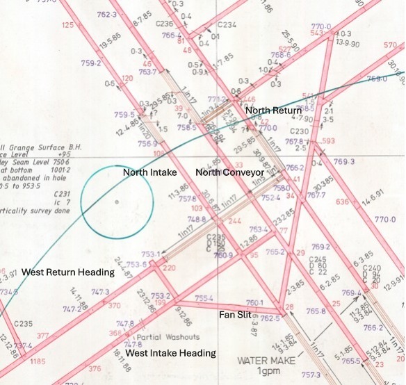
Plan showing all the faces worked at the West and South West of Riccall Mine
Mine plans attributions
Reproduced with the permission of © Intellectual property and copyright 2025 The Mining Remediation Authority. All rights reserved